
Rotary mooring conveying system

A conveying system, rotary conveying technology, used in transportation and packaging, ship parts, ships, etc., can solve problems such as unsupportable, large lateral load, equipment and line damage, etc.

Pending Publication Date: 2019-11-12
SHANDONG DINGSHENG SEIKO
View PDF0 Cites 2 Cited by
  • Summary
  • Abstract
  • Description
  • Claims
  • Application Information

AI Technical Summary

Problems solved by technology

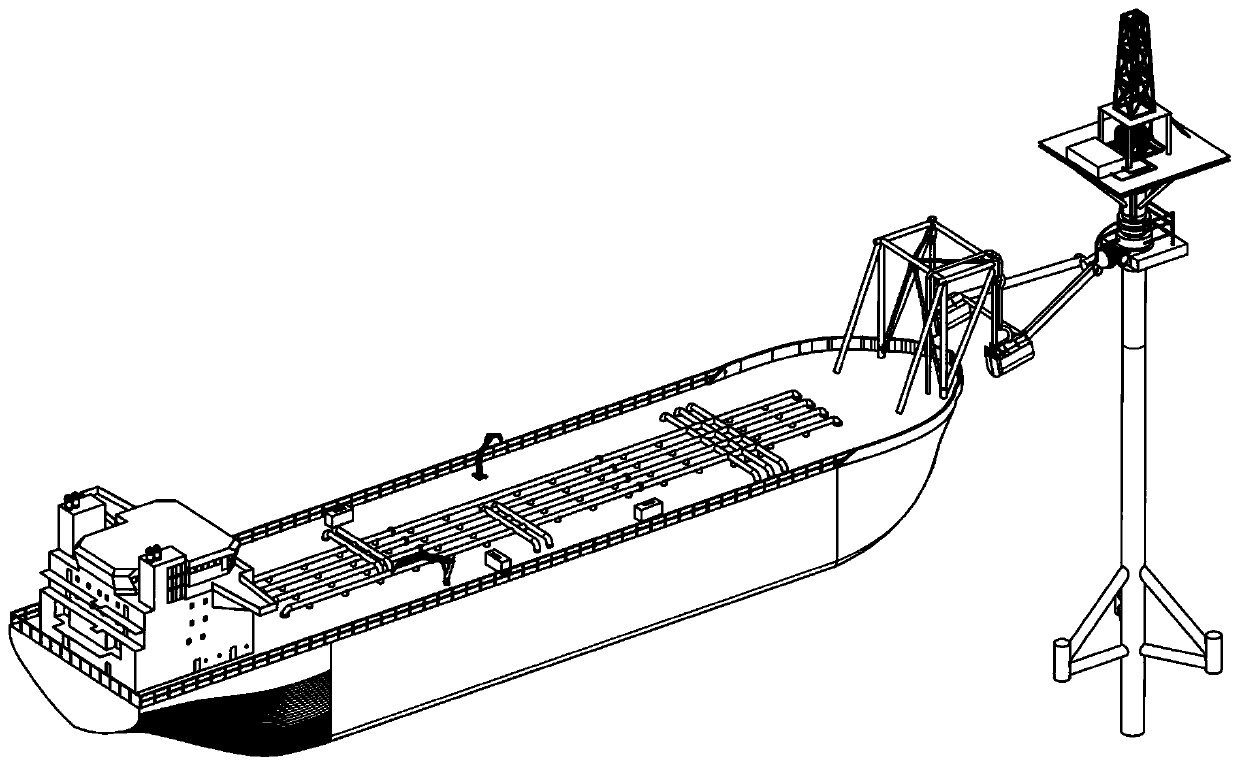
[0008] (2) The "bee-type" development model, that is, for small, isolated and small marginal oil and gas fields that are 20km away from the developed oilfields and cannot rely on the developed oilfields, mobile drilling (repair) wells, production, A model for the development of small-scale production devices that integrate power, oil storage, export, and life
The "bee-style" development mode can make marginal oil fields have certain economic benefits, but in order to realize the mobility of the platform, the shape of the platform will be limited, and it is difficult to allocate enough space for oil storage. Generally, the full-load reserves cannot exceed 2000 tons, which makes the number of shuttle tankers to pick up oil too frequent, thus reducing the economics of the entire oilfield development
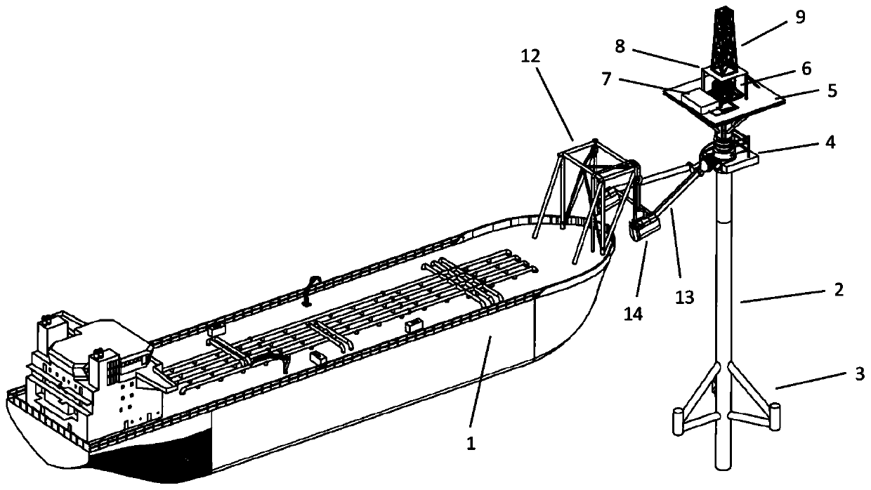
[0011] Another way of thinking is to consider connecting the storage and transportation ship with the jacket under normal production conditions, the jacket is used for production, and the storage and transportation ship is used to store crude oil, which not only has the functions of production, power, oil storage, export, and living , but in this way, the load on the storage and transportation ship in the production state is much greater than that of the oil storage device configured on the original platform, resulting in poor wind and wave resistance of the system as a whole, especially when the storage and transportation ship is in the state of transverse waves, the lateral load is extremely large , the violent rolling motion is likely to cause damage to the jacket or associated equipment and lines, resulting in accidents

Method used


Image

  • Rotary mooring conveying system
  • Rotary mooring conveying system
  • Rotary mooring conveying system

Examples


Embodiment Construction

[0095] In order to explain the overall concept of the present invention more clearly, the following will be described in detail by way of examples in combination with the accompanying drawings.

[0096] It should be noted that many specific details have been set forth in the following description so as to fully understand the present invention, but the present invention can also be implemented in other ways different from those described here, therefore, the protection scope of the present invention is not limited by the following limitations of the specific embodiments disclosed.

[0097] In addition, in the description of the present invention, it should be understood that the terms "center", "upper", "lower", "front", "rear", "left", "right", "vertical", "horizontal" ", "Top", "Bottom", "Inner", "Outer", "Axial", "Radial", "Circumferential" and other indicated orientations or positional relationships are based on the orientations or positional relationships shown in the dra...


PUM


Abstract

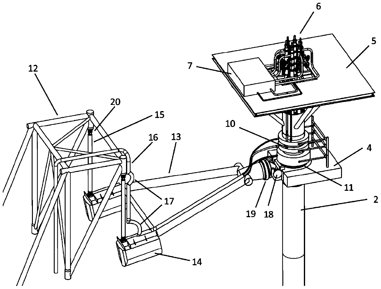
The invention discloses a rotary mooring conveying system used for oil production operation. The rotary mooring conveying system comprises a plurality of rotary conveying connectors. Each of the rotary conveying connectors comprises an inner conveying ring; an outer conveying ring, which can be rotated with respect to the inner conveying ring; a conveying structure, which is disposed between the inner conveying ring and the outer conveying ring, and can be used to maintain the conveying during the rotary process; an inner conveying unit, which is connected with the inner conveying ring; an outer conveying unit, which is connected with the outer conveying ring. The inner conveying rings of the rotary conveying connectors are fixedly connected together. In the ocean marginal oilfield development field, the rotary mooring conveying system can be used as the conveying equipment used for exploitation operation by aiming at the compatibility between the functions of the wellhead operation platforms and the mooring platforms.

Description

technical field [0001] The invention relates to the field of offshore oil and gas development, and relates to a rotary mooring transportation system. Background technique [0002] In my country's shallow waters, many marginal oil fields have been proven. The so-called marginal oil fields refer to those with small proven output (recoverable reserves of a single oil field are about 100,000 tons to 2 million tons), geographically dispersed and far away from other large oil fields, and economically developed by traditional development models. Less profitable oil fields. [0003] A complete oilfield development needs to have four processes of drilling (repair)-production-storage-transportation. The existing traditional shallow water oilfield development model in my country mainly includes the following parts: (1) single or multiple wellhead platforms; (2) production storage and offloading tanker (FPSO); (3) jacket and single point system for mooring FPSO; 4) The subsea pipeline...

Claims


Application Information

Patent Timeline
Patent Type & Authority Applications(China)
IPC IPC(8): B63B21/50E02B3/24
CPCB63B21/507E02B3/24
Inventor 高欣水岳涌
Owner SHANDONG DINGSHENG SEIKO
Learn More