Anode layer hall thruster with deeply-integrated hollow cathode

A technology of Hall thruster and hollow cathode is applied in the field of electric thruster and anode layer Hall thruster to achieve the effect of saving mass, simple and compact structure, and saving payload

Active Publication Date: 2019-11-12
BEIHANG UNIV
View PDF5 Cites 11 Cited by
  • Summary
  • Abstract
  • Description
  • Claims
  • Application Information

AI Technical Summary

Problems solved by technology

There is no research on how to reduce the

Method used


Image

  • Anode layer hall thruster with deeply-integrated hollow cathode
  • Anode layer hall thruster with deeply-integrated hollow cathode
  • Anode layer hall thruster with deeply-integrated hollow cathode

Examples


Embodiment Construction

[0019] In order to understand the above-mentioned purpose, features and advantages of the present invention more clearly, the present invention will be further described in detail below in conjunction with the accompanying drawings and specific embodiments. It should be noted that, in the case of no conflict, the embodiments of the present invention and the features in the embodiments can be combined with each other.

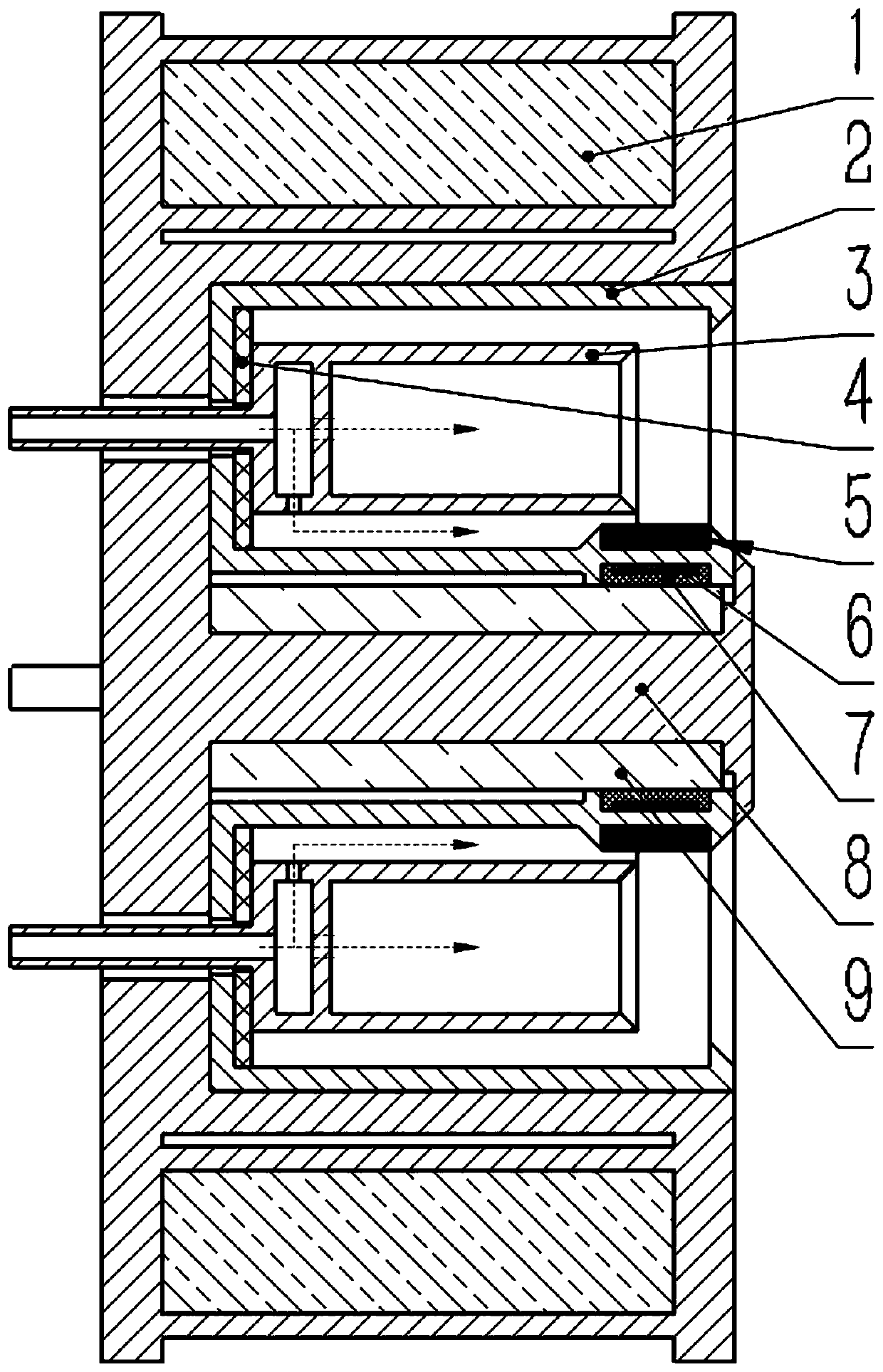
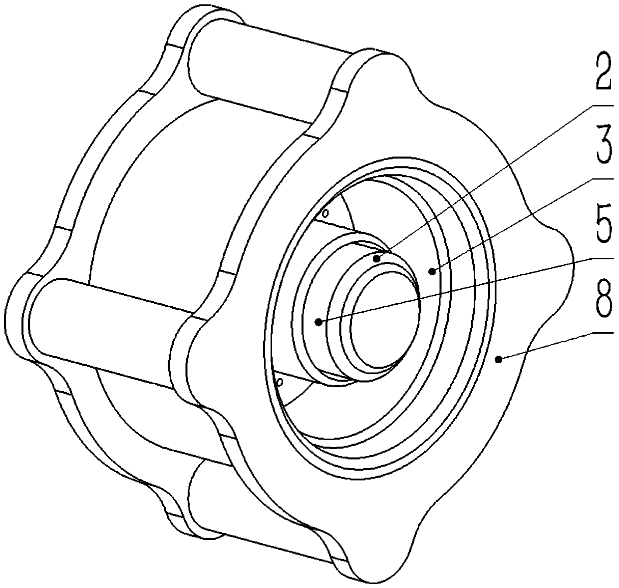
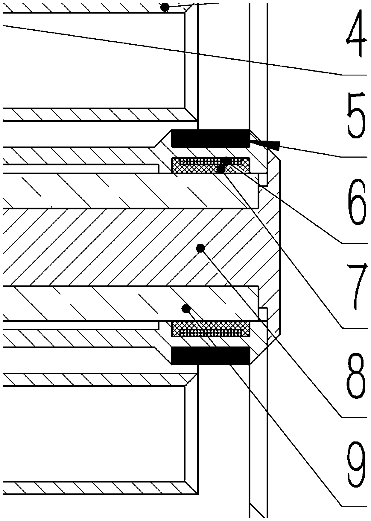
[0020] The invention is an anode layer Hall thruster with a hollow cathode deeply integrated. The main components of the device include outer magnetic coil 1, discharge chamber channel 2, anode 3, insulating gasket 4, emitter 5, heating wire 6, heat insulation layer 7, skeleton 8, and inner magnetic coil 9.

[0021] figure 1 The cross-sectional structure of the anode layer Hall thruster is shown, figure 2 The three-dimensional structure of the thruster is shown. Skeleton 8 is the main load-bearing component. There are four fixed cylinders on the outside of s...


PUM


Abstract

The invention discloses a thruster structure for deeply integrating a hollow cathode into an anode layer hall thruster. In the structure, the core part of the cathode is combined to the inner ring wall surface of the anode layer hall thruster, and the anode plays the role of an original cathode contact electrode. The thruster structure is used for replacing the combination of an original hall thruster and the hollow cathode, so that total mass of an electric propulsion system can be greatly reduced, and the payload is improved.

Description

Technical field: [0001] The invention belongs to the technical field of electric propulsion, and relates to an electric thruster, in particular to an anode layer Hall thruster with a deeply integrated hollow cathode. Background technique: [0002] The Hall thruster is a well-applied electric thruster, which has demonstrated its advantages of high specific impulse, long life, and high reliability in various space missions. Compared with the chemical propulsion system, the use of the Hall thruster is Energy supply can reduce the volume and weight of the system, reduce the quality of the propellant that needs to be carried, increase the actual payload of the satellite, and reduce the launch cost. There are currently two basic configurations of the Hall thruster, which are the Stationary Plasma Thruster (SPT) and the Thruster with Anode Layer (TAL). The core difference between the two is that, compared with In SPT, TAL has a shorter acceleration region, and the wall surface of ...

Claims


Application Information

Patent Timeline
IPC IPC(8): F03H1/00
CPCF03H1/0068
Inventor 汤海滨刘一泽曹帅章喆王一白任军学
Owner BEIHANG UNIV
Why Eureka
Try Eureka