Fluid shunt valve of biomass treatment system

A technology of biomass treatment and shunt valves, applied in valve details, multi-way valves, valve devices, etc., can solve the problem of high valve purchase cost, and achieve the effect of low manufacturing cost and manufacturing difficulty

Pending Publication Date: 2019-11-12
成都翠威新能源科技中心(有限合伙)
View PDF0 Cites 0 Cited by
  • Summary
  • Abstract
  • Description
  • Claims
  • Application Information

AI Technical Summary

Problems solved by technology

[0007] Aiming at the above-mentioned corresponding valves for the fluid branch transportation of the biomass treatment system, there is a technical problem of high purchase cost of the valve, the present invention provides a fluid branch valve for the biomass treatment system

Method used


Image

  • Fluid shunt valve of biomass treatment system
  • Fluid shunt valve of biomass treatment system
  • Fluid shunt valve of biomass treatment system

Examples


Embodiment 1

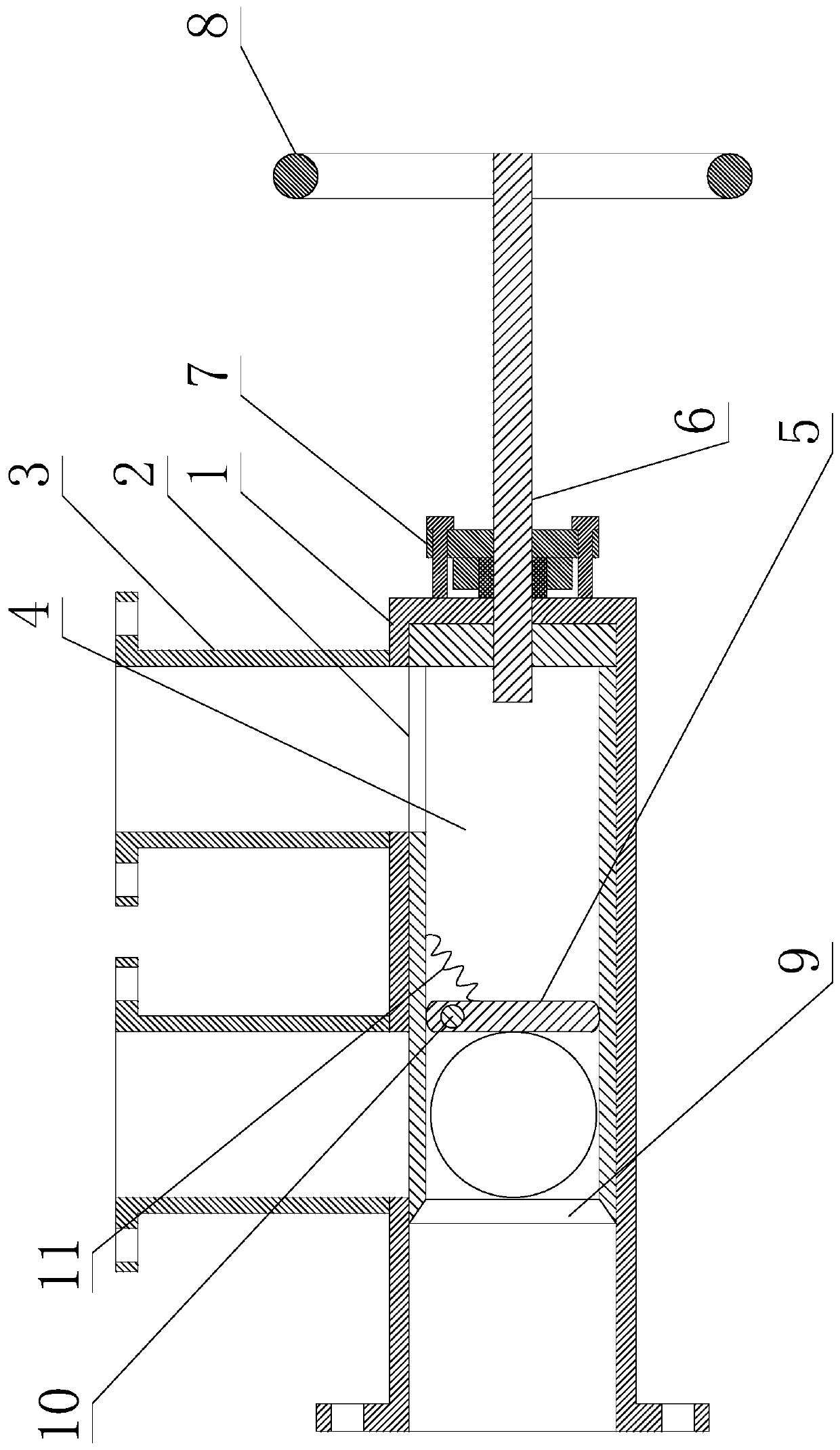
[0040] Such as Figure 1 to Figure 3 As shown, a fluid branch valve of a biomass treatment system includes a valve body and a valve plate 4 installed in the valve body. The valve body includes a dead leg section 1 and two outlet pipes 3. The inlet end of the outlet pipe 3 Both are connected on the side of the dead leg section 1;

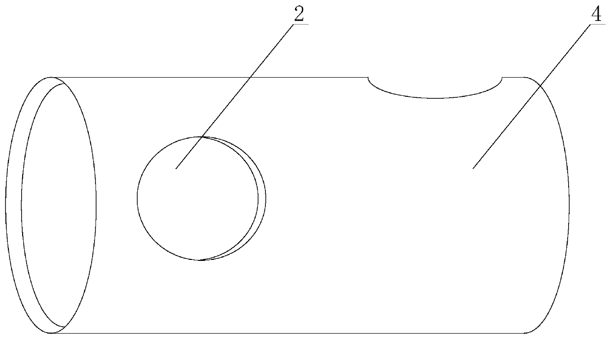
[0041] The valve plate 4 is cylindrical, the valve plate 4 is coaxial with the dead-leg section 1, and the valve plate 4 is installed in the dead-leg section 1, and the outer surface of the valve plate 4 is attached to the inner surface of the dead-leg section 1;

[0042] It also includes a driving mechanism for driving the valve plate 4 to rotate around its own axis. Among the two outlet pipes 3, one of the outlet pipes 3 is pipe A, and the other outlet pipe 3 is pipe B;

[0043] The valve plate 4 is also provided with two communication holes 2, and the communication holes 2 are through holes through the inside and outside of the valve plate 4;

...

Embodiment 2

[0049] The present embodiment is further limited on the basis of embodiment 1, as Figure 1 to Figure 3 As shown, in order to facilitate the laying of the fluid pipeline at the outlet end of the shunt valve, it is arranged that: in the circumferential direction of the dead-leg section 1, the two outlet pipes 3 are connected at the same position in the circumferential direction. As a person skilled in the art, in this solution, the two outlet pipes 3 are located at different axial positions of the dead-leg section 1 .

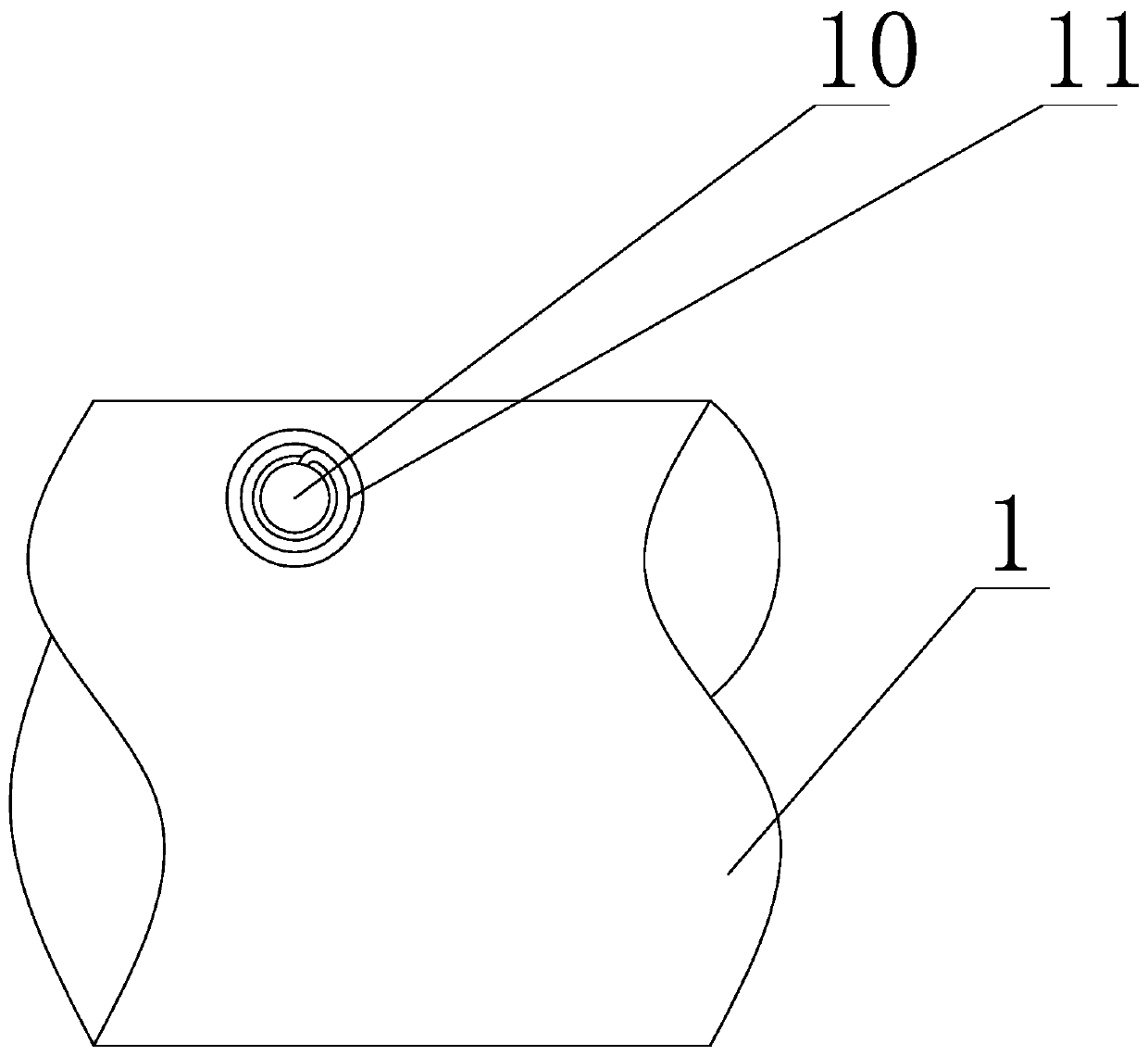
[0050] In order to avoid the accumulation of dust on the side of the valve plate 4 close to the closed end of the dead-leg section 1 when the outlet pipe 3 close to the inlet end of the dead-leg section 1 is connected to the dead-leg section 1, causing the other outlet pipe 3 to conduct with the dead-leg section 1 When the valve plate 4 is blocked by the accumulated dust, it is set to: also include a flap 5 installed in the valve plate 4 through the second rotat...


PUM


Abstract

The invention discloses a fluid shunt valve of a biomass treatment system. The fluid shunt valve involves a valve body and a valve plate, wherein the valve body comprises a blind tube section and twooutlet tubes; the valve plate is cylindrical, the valve plate is arranged in the blind tube section, and the outer surface of the valve plate is attached to the inner surface of the blind tube section; the fluid shunt valve further involves a driving mechanism, among the two outlet tubes, one outlet tube is the tube A, and the other outlet tube is the tube B; two communication holes are formed inthe valve plate; when one of the communication holes is in the conduction state for conducting the tube A and the blind tube section, the other communication hole is staggered with the tube B, and thetube B and the blind tube section are in a truncated state; and when one of the communication holes is in the conduction state for conducting the tube B and the blind tube section, the other communication hole is staggered with the tube A, and the tube A and the blind tube section are in a truncated state. The shunt valve is simple in structure, low in processing and manufacturing cost, can be obtained through modification in an existing pipeline and is easy to drive so as to change the conduction state.

Description

technical field [0001] The invention relates to the technical field of valves, in particular to a fluid branch valve of a biomass treatment system. Background technique [0002] With the rapid development of my country's social economy, the acceleration of urbanization and the rapid improvement of people's living standards, the garbage and waste generated in the process of urban production and life have also increased rapidly, and the situation of domestic garbage occupying land and polluting the environment has become more and more obvious. The massive increase of household garbage makes garbage disposal more and more difficult. In addition, a large amount of straw obtained in agricultural production, and a large amount of branches and sawdust obtained in wood production, one of the traditional methods is to use direct incineration to obtain heat for reuse, and the resulting environmental pollution and other problems have gradually caused social problems widespread attentio...

Claims


Application Information

Patent Timeline
IPC IPC(8): F16K11/085F16K11/10F16K27/06F16K31/60F16K41/02
CPCF16K11/0856F16K11/10F16K27/065F16K31/60F16K41/02
Inventor 彭琪彭罡
Owner 成都翠威新能源科技中心(有限合伙)
Why Eureka
Try Eureka