
Sowing device and mobile operation equipment

The technology of conveying device and power mechanism is applied in the direction of launching device, fertilizing device, and device for catching or killing insects, etc. It can solve the problems of difficult manufacturing, failure of spreading device, and high failure rate, so as to reduce the cost of use and maintenance, The effect of reducing manufacturing difficulty and manufacturing cost

Active Publication Date: 2022-05-06
SUZHOU EAVISION ROBOTIC TECH CO LTD
View PDF9 Cites 0 Cited by
  • Summary
  • Abstract
  • Description
  • Claims
  • Application Information

AI Technical Summary

Problems solved by technology

However, in the process of conveying materials by the spreader using the auger conveyor in the prior art, the viscous material will block the auger conveyor, which will cause the spreading device to fail
[0003]In addition, the traditional spreader adopts an integral mechanism, so there are defects that it is difficult to manufacture and expensive, and there is especially a technical problem that it cannot be disassembled as a whole, so that Further leading to the inability to clean or clean the clogged area inside
As a result, the spreader that conveys the material by the auger conveyor has the defects of low spreading efficiency and high failure rate, which seriously affects the continuous spreading operation of the spreader

Method used


Image

  • Sowing device and mobile operation equipment
  • Sowing device and mobile operation equipment
  • Sowing device and mobile operation equipment

Examples


Embodiment Construction

[0045] The present invention will be described in detail below in conjunction with the implementations shown in the drawings, but it should be noted that these implementations are not limitations of the present invention, and those of ordinary skill in the art based on the functions, methods, or structural changes made by these implementations Equivalent transformations or substitutions all fall within the protection scope of the present invention.

[0046] It should be understood that in this application the terms "central", "longitudinal", "transverse", "length", "width", "thickness", "upper", "lower", "front", "rear" , "Left", "Right", "Vertical", "Horizontal", "Top", "Bottom", "Inner", "Outer", "Axial", "Radial", etc. indicate the orientation or positional relationship as Based on the orientation or positional relationship shown in the drawings, it is only for the convenience of describing the technical solution and simplifying the description, and does not indicate or imp...


PUM


Abstract

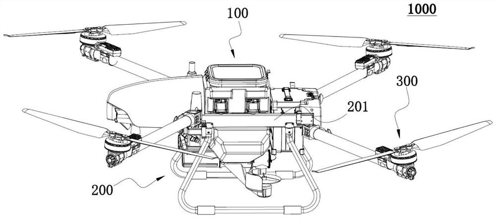
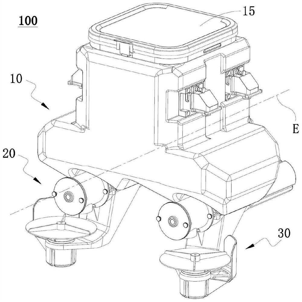
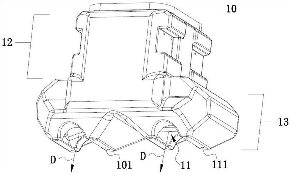
The invention discloses a sowing device and mobile operation equipment. The sowing device comprises a material storage box, at least one material conveying device embedded in the bottom of the material storage box, and a dispersing assembly, the storage box is provided with a first discharge port; the material conveying device comprises an inner shell, an outer shell partially containing the inner shell in the axial direction, an auger assembly axially arranged in the inner shell and a first power mechanism driving the auger assembly. A cleaning opening is formed in the outer shell, the inner shell and the outer shell are connected in a screwed mode to jointly form a feeding channel for materials to be conveyed into the material conveying device from the first discharging opening, and the inner shell and the outer shell are axially separated so that the feeding channel and the first discharging opening can be exposed through the cleaning opening. According to the scattering device, the inner shell is separated from the outer shell in the axial direction, materials stacked or retained at the bottom of the material conveying device and the bottom of the material storage box can be cleaned and washed through the cleaning opening, and meanwhile the manufacturing difficulty and the manufacturing cost of the scattering device are reduced.

Description

technical field [0001] The invention relates to the technical field of plant protection equipment, in particular to a spreading device and mobile operation equipment. Background technique [0002] In agricultural plant protection operations, the sowing operations of seeds, fertilizers and other materials mainly rely on manual sowing and sowing by sowing machines. The spreader can use the auger conveyor to push the material, and the material can be thrown out and spread by the rotating spreading disc. The auger conveyor pushes the material through the rotating helical blades for screw conveying. However, in the prior art, when the spreading machine using the auger conveyor conveys the material, the viscous material will block the auger conveyor, which in turn causes the spreading device to malfunction. [0003] In addition, the traditional spreader adopts an integral mechanism, so it has the defects of high manufacturing difficulty and high cost, and especially the technica...

Claims


Application Information

Patent Timeline
IPC IPC(8): A01M9/00A01C7/08A01C15/08B64D1/16B65G33/14
CPCA01M9/0053A01M9/0084A01C7/085A01C15/08B64D1/16B65G33/14B65G2201/04
Inventor 邵洋赵龙刘厚臣
Owner SUZHOU EAVISION ROBOTIC TECH CO LTD
Learn More