Thermal-imager installation reference surface deviation elimination installation and adjustment method

A technology for eliminating installation datum and deviation, which is applied in the technological field of eliminating the deviation of the installation datum plane of thermal imagers. The scrapping of parts, the elimination of installation datum deviation, and the effect of reducing the difficulty of process operation

Active Publication Date: 2019-11-12
KUNMING NORTH INFRARED TECH CO LTD
View PDF15 Cites 0 Cited by
  • Summary
  • Abstract
  • Description
  • Claims
  • Application Information

AI Technical Summary

Problems solved by technology

[0011] 1. It is labor-intensive and time-consuming. Repeated testing and shoveling the installation surface will take up 2 to 3 hours of working time for the test bench, an inspector and a fitter;
[0012] 2. It will destroy the flatness of the four mounting surfaces of the thermal imager
If the accuracy of the installation datum surface is to be qualified, and the flatness of the four installation surfaces is also qualified, an 8-level fitter level is required, and the operation is extremely difficult
[0013] 3. When the deviation of the installation reference plane is large, that is, the deviation ≥ 40 steps, that is, the main shell of 2mrad, because the shoveling amount of the installation surface is already greater than the height of the installation surface H by 1mm, the main shell will be damaged, and the main shell worth tens of thousands of yuan The shell can only be scrapped

Method used


Image

  • Thermal-imager installation reference surface deviation elimination installation and adjustment method
  • Thermal-imager installation reference surface deviation elimination installation and adjustment method
  • Thermal-imager installation reference surface deviation elimination installation and adjustment method

Examples


Embodiment 1

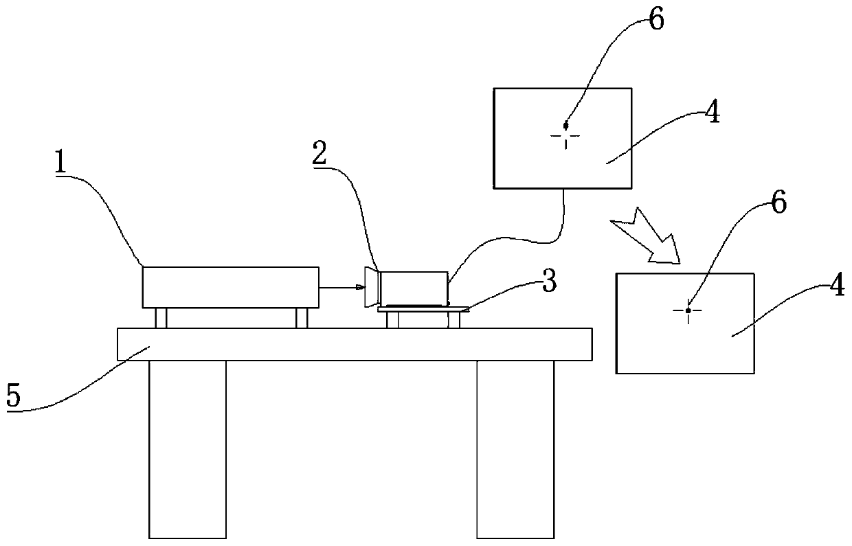
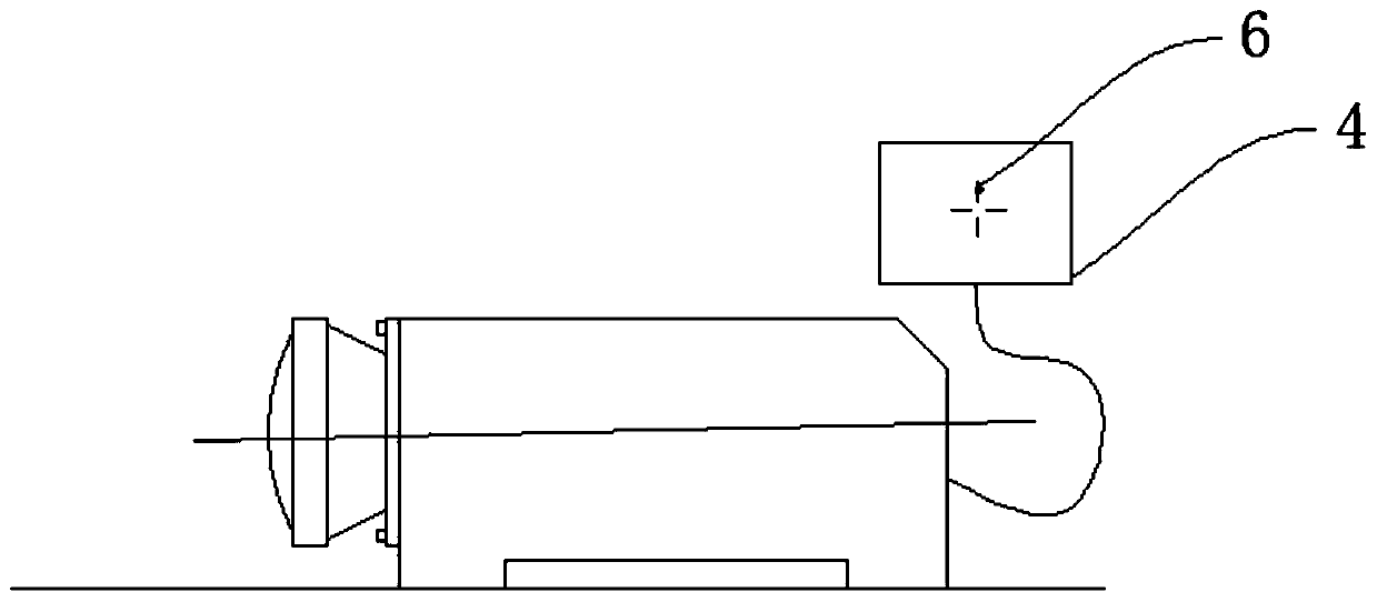
[0038] Example 1: When the type A product measures the deviation of the installation reference plane, the imaging point 6 of the small field of view deviates 34 steps upward from the center of the reticle, and the index is unqualified, such as image 3 As shown, it needs to be adjusted.

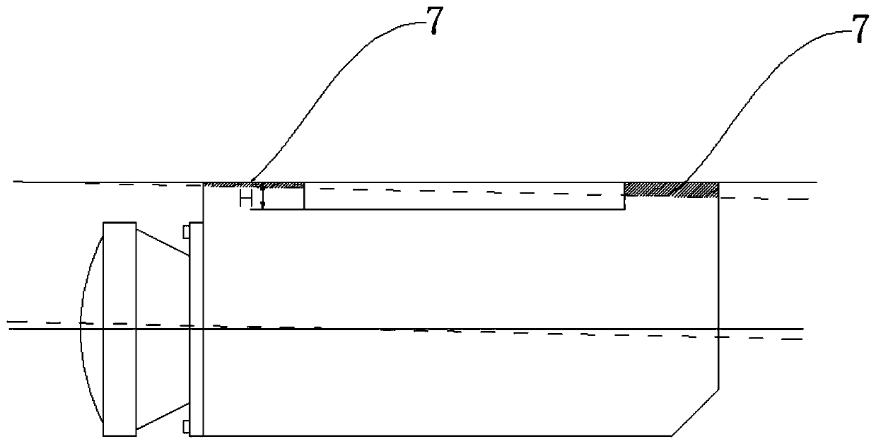
[0039] The small field of view imaging point 6 deviates upward relative to the moving reticle line. The gasket 8 is specifically installed between the objective lens holder and the main housing under the objective lens. Copper gaskets 8 are respectively placed under the two screws. Figure 4 shown. Refer to Table 1, step 34 is about to pad 0.25mm thick gasket 8. After the gasket is measured, the deviation index of the installation reference plane is 0.05mrad, which meets the index requirement of <0.5mrad, and the inspection is qualified.

Embodiment 2

[0040] Example 2: When the type B product measures the deviation of the installation reference plane, the imaging point 6 of the small field of view deviates 21 steps downward from the center of the reticle, and the index is unqualified, such as Figure 5 As shown, it needs to be adjusted.

[0041] The small field of view imaging point 6 deviates downward relative to the moving reticle line. The gasket 8 is specifically installed between the objective lens holder and the main housing on the objective lens. Copper gaskets are respectively placed on the two screws. Figure 6 shown. Look up Table 1, step 21 needs to pad about 0.15mm thick gasket 8. Measure the deviation of the installation datum plane in 3 steps after the copper sheet, that is, the deviation of the index is 0.15mrad, which meets the index of <0.5mrad, and the inspection is qualified.


PUM


Abstract

The invention discloses a thermal-imager installation reference surface deviation elimination installation and adjustment method, and relates to a thermal-imager calibration and installation technology, and particularly to technology of thermal-imager installation reference surface deviation elimination. According to the method of the invention, a place between an objective lens seat and a main shell body is padded with a correspondingly sized gasket according to deviation distance and an upper/lower position of deviation of a small-view-field imaging point relative to a moving dividing line to achieve the purpose of installation and adjustment. The method of the invention can quickly and conveniently eliminate thermal-imager installation reference surface deviation in real time, reduces rework, and saves production costs.

Description

technical field [0001] The invention relates to a thermal imager calibration technology, in particular to a process technology for eliminating the deviation of a thermal imager installation reference plane. Background technique [0002] The thermal imager installation datum accuracy index is an index to measure the parallelism deviation between the thermal imager’s small field of view optical axis and the thermal imager’s installation bottom surface. The inspection process of the benchmark index is: [0003] S1: Measure the deviation of the installation reference plane on the test bench; [0004] S2: The thermal imager is powered off; [0005] S3: Use a shovel on the fitter's table to shovel the corresponding installation bottom surface of the main housing, first shovel the two installation surfaces at the rear of the thermal imager, and then shovel the 4 installation surfaces to ensure the flatness of the 4 installation surfaces; [0006] S4: Measure the deviation again ...

Claims


Application Information

Patent Timeline
Patent Type & Authority Applications(China)
IPC IPC(8): G01J5/00
CPCG01J5/00G01J5/80
Inventor 杨庆华薛立和徐安健赖富相李学宽张益杨锡柱刘海曲文丹霞
Owner KUNMING NORTH INFRARED TECH CO LTD
Why Eureka
Try Eureka