MEMS (Micro Electro Mechanical System) gyroscope drive/detecting modal preset performance anti-interference control method

A technology for detecting modal and preset performance, applied in gyroscope/steering sensing equipment, gyro effect for speed measurement, adaptive control, etc. Guarantee and other issues

Active Publication Date: 2019-11-12
ZHONGBEI UNIV
View PDF3 Cites 3 Cited by
  • Summary
  • Abstract
  • Description
  • Claims
  • Application Information

AI Technical Summary

Problems solved by technology

[0004] The present invention provides a MEMS gyroscope drive / detection mode preset performance anti-interference control method in order to solve the problem of robust tracking control of MEMS gyroscope mass block under strong interference environment, which is summarized as follows: (1) introduce preset Based on the performance control method, through the boundary function and error conversion technology, it effectively solves the problem of a priori guarantee of gyroscope drive / detection modal dynamic / steady-state performance that cannot be achieved by existing control methods in a strong interference environment; (2) further combining The virtual control quantity of the linear displacement loop is designed with the idea of ​​dynamic surface control, and the purpose of precise tracking of the given linear displacement command of the MEMS gyroscope is achieved; (3) The linear velocity and the lumped disturbance of the MEMS gyroscope are simultaneously reconstructed by constructing an extended state observer , to improve the robustness of the MEMS gyroscope measurement and control system under the framework of output feedback control

Method used


Image

  • MEMS (Micro Electro Mechanical System) gyroscope drive/detecting modal preset performance anti-interference control method
  • MEMS (Micro Electro Mechanical System) gyroscope drive/detecting modal preset performance anti-interference control method
  • MEMS (Micro Electro Mechanical System) gyroscope drive/detecting modal preset performance anti-interference control method

Examples


Embodiment Construction

[0061] The present invention will be further described below in conjunction with the accompanying drawings and specific embodiments.

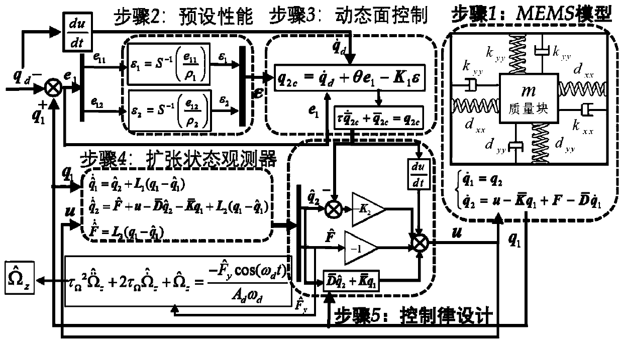
[0062] A MEMS gyroscope drive / detection mode preset performance anti-interference control method, comprising the following steps:

[0063] (1) Establish a strict feedback MEMS gyroscope dynamic model under the influence of external disturbance, parameter uncertainty and modal coupling multi-source disturbance;

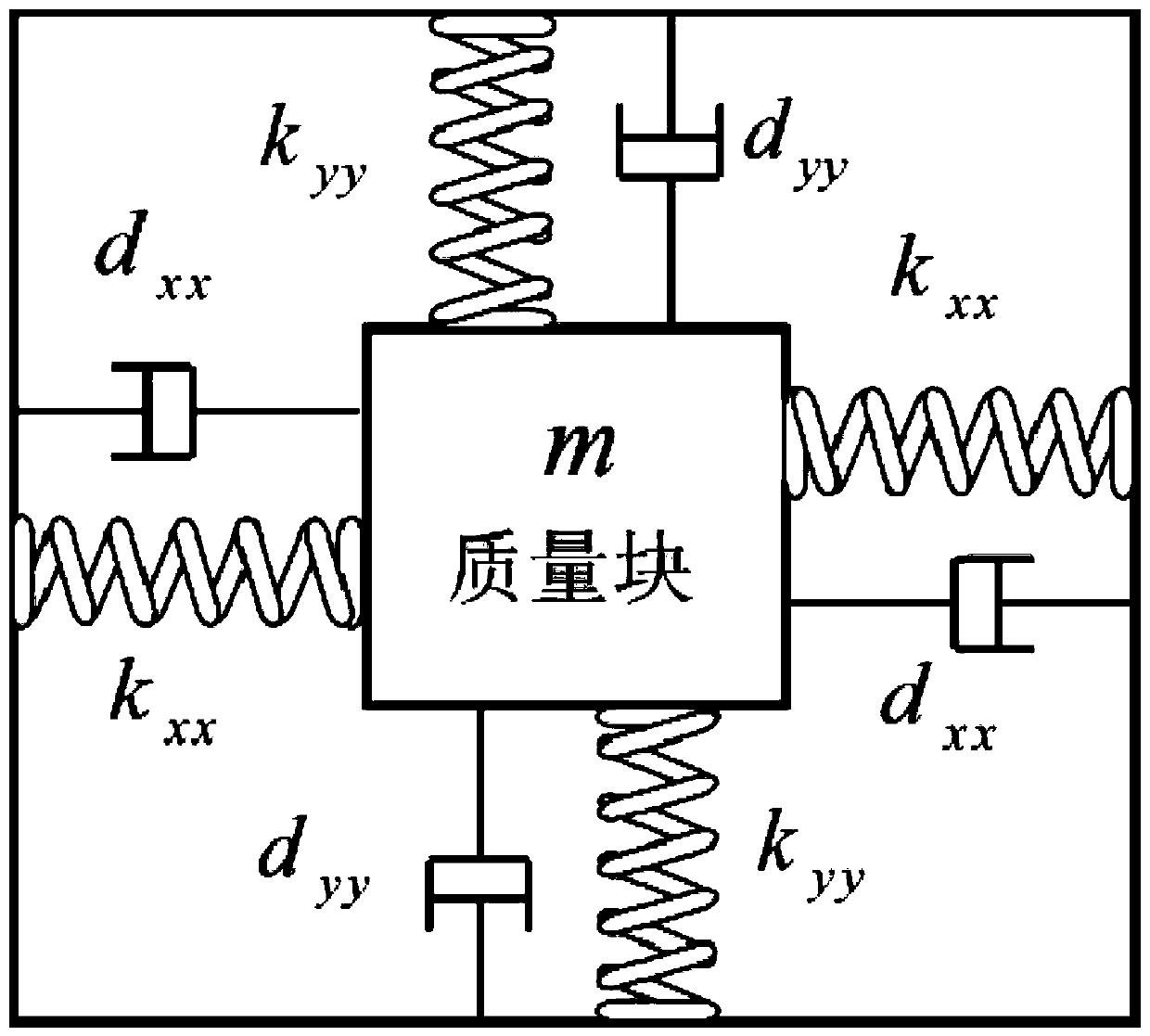
[0064] Establish a MEMS gyroscope dynamic model without external disturbance:

[0065]

[0066] Among them, m is the mass of the mass block, x and y are the linear displacement of the drive / detection mode gyroscope mass block respectively, with are the linear velocities of driving / detecting modal gyroscope masses, k xx and k yy are the two modal spring coefficients, d xx and d yy are the two modal damping coefficients, Ω z is the angular velocity to be sensitive, u x and u y It is the control input of the gyro drive / detect...


PUM


Abstract

The invention discloses an MEMS (Micro Electro Mechanical System) gyroscope drive / detecting modal preset performance anti-interference control method, and relates to the technical field of automatic control of MEMS gyroscopes. The overview of the method comprises the following steps: (1) introducing a preset performance controlling method, so that the difficult problems that gyroscope drive / detecting modal dynamic state / steady-state performance prior guarantee cannot be realized in a strongly interfering environment by the existing control method are effectively solved through a boundary function and an error conversion technology; (2) designing a linear displacement loop virtual control amount by further combining a dynamic plane control thought, so that the purpose of precisely trackinga given linear displacement command of an MEMS gyroscope is achieved; and (3) reconstructing the linear viscosity and the lumped interference of the MEMS gyroscope simultaneously by constructing an extended state observer, so that the robustness of an MEMS gyroscope measurement and control system under an output feedback control framework is improved. According to the MEMS gyroscope drive / detecting modal preset performance anti-interference control method, the linear displacement dynamic state / steady-state tracking performance under multi-source interference is improved, and the angular velocity measurement accuracy is improved.

Description

technical field [0001] The invention relates to the technical field of automatic control of MEMS gyroscopes, in particular to a MEMS gyroscope drive / detection mode preset performance anti-interference control method, which is applied to strong external disturbances such as shock and vibration, coupling between gyroscope modes, and Guaranteed Robust Tracking Control of MEMS Gyroscope Mass under Parameter Uncertainty Environment. Background technique [0002] MEMS (Micro electromechanical system, abbreviated as MEMS) gyroscope, as an inertial sensor used to measure angular rate, has the advantages of small size, low cost, mass production, easy signal processing circuit integration, high precision and high reliability. It is not only the preferred angular rate sensor for the measurement of carrier angular rate information after the launch of military conventional weapons (such as artillery, tank guns) and new kinetic energy weapons (such as electromagnetic rail guns), but also ...

Claims


Application Information

Patent Timeline
IPC IPC(8): G05B13/04G01C19/5776
CPCG05B13/042G01C19/5776
Inventor 邵星灵杨卫曹志斌刘珊
Owner ZHONGBEI UNIV
Why Eureka
Try Eureka