
Air-cooled heat-dissipation device of PET system

A heat dissipation device and air cooling technology, applied in medical science, instruments for radiological diagnosis, diagnosis, etc., can solve the problems of high external air efficiency, high temperature, affecting the overall performance, etc., and achieve high heat dissipation efficiency and good uniformity. Effect

Pending Publication Date: 2019-11-15
FMI MEDICAL SYST CO LTD
View PDF2 Cites 5 Cited by
  • Summary
  • Abstract
  • Description
  • Claims
  • Application Information

AI Technical Summary

Problems solved by technology

However, the design of the peripheral air duct and the inner cavity air duct in this scheme will cause a large difference in the cooling air temperature or flow rate supplied to each detector module on the ring, which will affect the temperature uniformity of each detector module, thereby affecting the overall Performance; the air cooler extracts the air heated by the core components of the detector, and the temperature may be higher than the room temperature outside the outer cover. It is not efficient to directly extract external air

Method used


Image

  • Air-cooled heat-dissipation device of PET system
  • Air-cooled heat-dissipation device of PET system
  • Air-cooled heat-dissipation device of PET system

Examples


Embodiment Construction

[0027] refer to Figure 1 to Figure 10 A specific implementation of the air-cooled heat dissipation device for a PET system of the present invention will be further described.

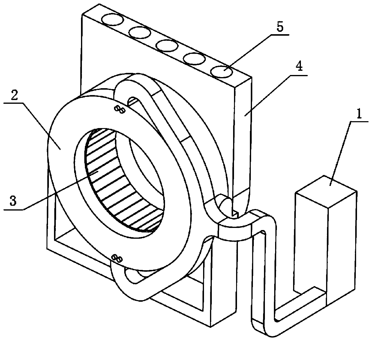
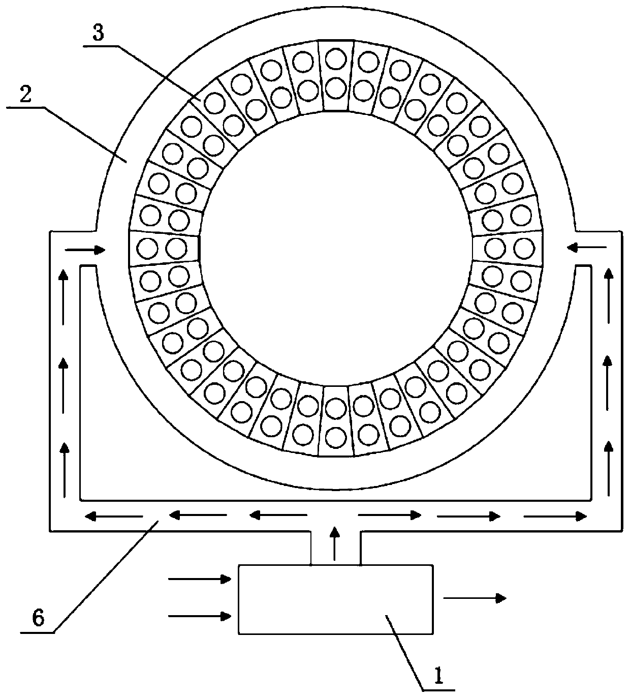
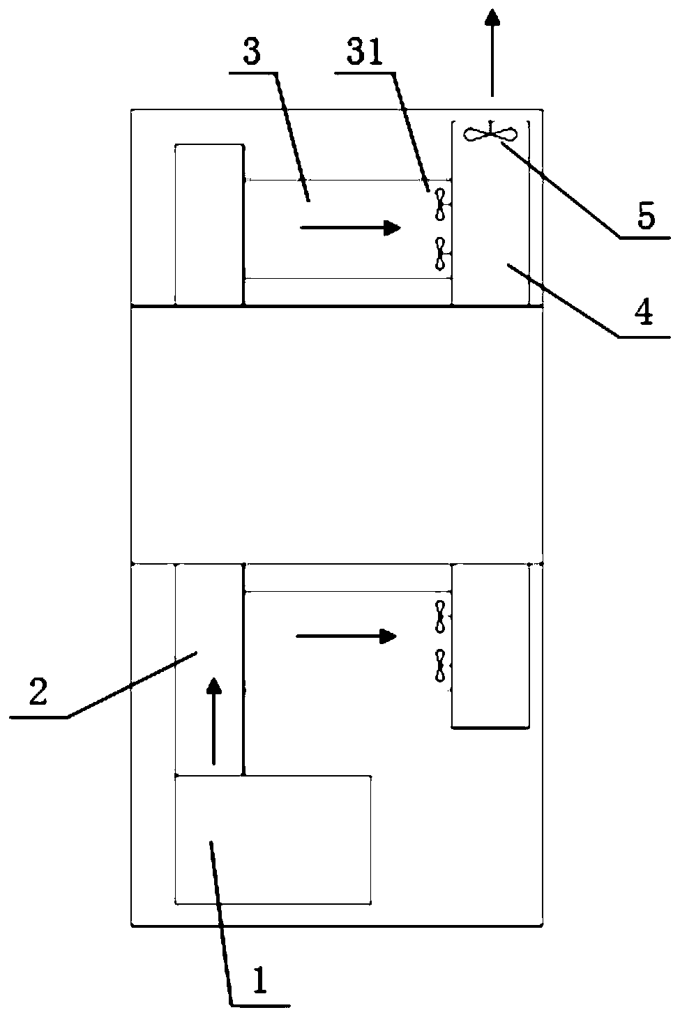
[0028] A kind of PET system air cooling heat dissipation device, such as figure 1 As shown, the PET system includes a scanning ring and an installation base installed in the scanning ring. Several detectors 3 are installed on the installation base to form a detector ring. The air-cooled heat dissipation device includes The air inlet channel 2 and the air outlet channel 4 on both sides of the scanning ring, the air inlet channel 2 is provided with a number of air inlets 21, and the air inlet 21 is connected to the air cooling device 1 through the air inlet pipe 6, so The inside of the air inlet passage 2 is provided with an inner air inlet passage 22 communicating with the air inlet 21, and the side of the inner air inlet passage 22 that fits the end surface of the detector 3 is provided with a plurali...


PUM


Abstract

The invention discloses an air-cooled heat-dissipation device of a PET system. The PET system includes a scanning ring and a mounting base installed in the scanning ring. A plurality of detectors is installed on the mounting base to form a detector ring, the air-cooled heat-dissipation device includes an air inlet channel and an air outlet channel respectively located on both sides of the scanningring, the air inlet channel is provided with a plurality of air inlets 1, the air inlets 1 are connected with an air cooling device through air inlet pipes, the inside of the air inlet channel is provided with an inner air inlet channel communicating with the air inlet 1, and a plurality of air outlets 1 can be provided on the surface where the inner air inlet channel and the end face of the detector are applied. A detector is provided with an air inlet device, two ends of the detector are respectively provided with an air inlet 2 and an air outlet 2, the air inlet 2 is in communication withthe inner air inlet channel, the air outlet 2 is in communication with the air outlet channel, and the top of the air outlet channel is provided with an exhaust device. The cooling air can be subjected to heat radiation and cooling on the detector according to a predetermined flow channel, and the device has a simple structure, high heat-dissipation efficiency and uniform internal temperature.

Description

technical field [0001] The invention relates to the technical field of medical imaging equipment, and more specifically relates to an air-cooled heat dissipation device for a PET system. Background technique [0002] The detectors of the PET system are evenly distributed on the entire circumference of the ring, and the heat and power consumption is scattered. After the outer cover is covered, the internal air flow field is relatively chaotic, and the cold air from the outside cannot be well guided to the detector air inlet, and the detector air outlet comes out. The hot air cannot be effectively discharged to the outside of the housing, which will cause the temperature of the detector to be high and affect various performance indicators and image quality of the system. At the same time, the operation of CT will also affect the heat dissipation of the PET system. In the patent documents whose publication numbers are CN103860187B and CN105704982B, it is announced that a centr...

Claims


Application Information

Patent Timeline
Patent Type & Authority Applications(China)
IPC IPC(8): A61B6/03
CPCA61B6/037A61B6/4488
Inventor 许建青马兴江金坚诚
Owner FMI MEDICAL SYST CO LTD
Learn More