
Splicing method for splicing multiple mold core loosen pieces to form annular mold core

A core and live block technology, applied in the direction of core, mold composition, mold, etc., can solve the problem of affecting the bonding quality of the finished annular ceramic core, the liquid glue does not have high temperature resistance, and the error of the joint surface is large, etc. problems, to achieve the effect of improving the efficiency of splicing and assembly, reducing errors and ensuring the quality of bonding

Inactive Publication Date: 2019-11-15
GUIZHOU ANJI AVIATION PRECISION CASTING
View PDF7 Cites 1 Cited by
  • Summary
  • Abstract
  • Description
  • Claims
  • Application Information

AI Technical Summary

Problems solved by technology

Some annular castings need to be placed with annular ceramic cores. Due to the characteristics of brittle and hard ceramic cores, it is difficult for thin-walled annular ceramic cores to be molded as a whole, and they are easy to break during the process. Therefore, the ceramic cores need to be separated Make several core blocks, and then splice these core blocks into annular ceramic cores. In the prior art, liquid glue is usually used for the splicing of annular ceramic cores. However, the existing liquid glue generally does not have High temperature resistance, limited bonding strength, and during the bonding process, each core block is not positioned in space, which is likely to cause large errors in the joint surface, affecting the bonding quality of the finished annular ceramic core, and once the ring The bonding quality of the ceramic core is defective, which will make it difficult to release the casting after molding

Method used


Image

  • Splicing method for splicing multiple mold core loosen pieces to form annular mold core

Examples


Embodiment Construction

[0017] The technical solution of the present invention is further described below, but the scope of protection is not limited to the description.

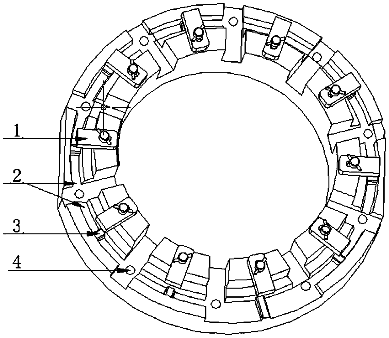
[0018] Such as figure 1 As shown, the present invention provides a kind of splicing method that several core loose blocks are spliced ​​into annular core, comprises the following steps:

[0019] A splicing plate is provided, and a closed annular positioning ring 2 is arranged on the splicing plate. Several limit card slots 3 are arranged on the position ring 2. The number of limit card slots 3 is equal to the number of core blocks, and the limit card The contour of the inner wall of the groove 3 corresponds to the outline of the surface part of the core block one by one. Bonded together, after the adhesive has set, all the core pieces are spliced ​​to form an annular core.

[0020] Further, it is preferred that the raw materials for the adhesive include bauxite and silica sol. Adopting the technical solution of the invention, th...


PUM


Abstract

The invention provides a splicing method for splicing multiple mold core loose pieces to form an annular mold core. The splicing method comprises the steps of providing a splicing disc, wherein a closed annular positioning ring is arranged on the splicing disc, a plurality of limiting clamping grooves are formed in the positioning ring, the number of the limiting clamping grooves is equal to the number of the mold core loose pieces, and the contour of the inner wall of each limiting clamping groove corresponds to part of the contour of the surface of each mold core loose piece one by one; firstly, sleeving the mold core loose pieces in the limiting clamping grooves correspondingly one by one; bonding the two adjacent core loose pieces together by using an adhesive; and after the adhesive is coagulated, splicing the mold core loose pieces to form the annular mold core. By adopting the technical scheme, the accurate positioning of the multiple mold core loose pieces is achieved through the splicing disc, so that the positioning error is reduced, and the bonding quality of the annular mold core is improved; and by using the adhesive containing bauxite and silica sol raw materials, compared with the prior art, the coagulating time is shortened, the bonding strength is improved, and the bonding quality of the annular mold core is guaranteed..

Description

technical field [0001] The invention relates to the technical field of casting technology, in particular to a splicing method for splicing several core loose blocks to form an annular core. Background technique [0002] In the investment casting process, ceramic cores are usually used to form the cavity of castings with complex shapes or difficult to form, as a special process method to simplify the difficulty of the process, reduce the cost and improve the qualified rate of castings. Some annular castings need to be placed with annular ceramic cores. Due to the characteristics of brittle and hard ceramic cores, it is difficult for thin-walled annular ceramic cores to be molded as a whole, and they are easy to break during the process. Therefore, the ceramic cores need to be separated Make several core blocks, and then splice these core blocks into annular ceramic cores. In the prior art, liquid glue is usually used for the splicing of annular ceramic cores. However, the exi...

Claims


Application Information

Patent Timeline
Patent Type & Authority Applications(China)
IPC IPC(8): B22C9/10
CPCB22C9/103
Inventor 李晏涛
Owner GUIZHOU ANJI AVIATION PRECISION CASTING
Learn More