An assembly and positioning structure of the main combustion hole liner on the flame tube

A technology of positioning structure and main combustion hole, applied in the field of assembly and processing, can solve the problems of large assembly error of part slot position, large deviation of bush slot position, poor axial consistency of slot, etc. The effect of no rework and repair, stable processing quality

Active Publication Date: 2022-02-11
CHINA HANGFA GUIZHOU LIYANG AVIATION POWER CO LTD
View PDF0 Cites 0 Cited by
  • Summary
  • Abstract
  • Description
  • Claims
  • Application Information

AI Technical Summary

Problems solved by technology

Considering the quality of assembly and processing, manual scribing is used for assembly processing, the parts are complex and irregular, and the error of manual scribing is large. If manual assembly is used, visual inspection and scribing position will cause secondary assembly errors. , the assembly error of the slot position of the part is large, which will cause more than 20 bushings to be assembled and welded, the position of the bushing slot deviates greatly, and the axial consistency of the slot is poor
From the perspective of processing efficiency, due to the large number of bushes that need to be assembled and welded, the workload is very large, resulting in a very long processing cycle. According to the on-site processing conditions, it takes more than 8 hours to assemble and weld the main combustion hole bushing of a flame tube , a sheet metal worker is needed for scribing, assembly and correction, and a welder is needed for positioning

Method used


Image

  • An assembly and positioning structure of the main combustion hole liner on the flame tube
  • An assembly and positioning structure of the main combustion hole liner on the flame tube
  • An assembly and positioning structure of the main combustion hole liner on the flame tube

Examples


Embodiment Construction

[0020] Below in conjunction with accompanying drawing and specific embodiment the invention is further introduced:

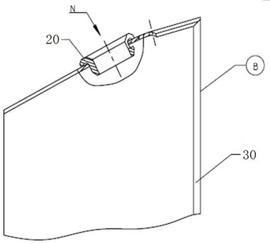
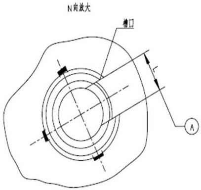
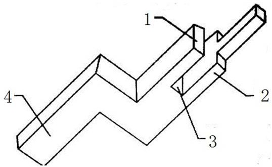
[0021] As shown in the figure, there is a circle of holes on the wall of the flame cylinder 30, and a main combustion hole bushing 20 needs to be installed in each hole. The main combustion hole bushing 20 is C-shaped, and the direction of the notch needs to be consistent. A positioning fixture 10 is designed to control the notch direction of the main combustion hole liner 20. The positioning fixture 10 is in a Z-shape as a whole, with one end being the handle part 4 and the other end being a clamping part. The outer splint 2, the positioning pin 5 extends from the outer splint 2, the width of the positioning pin 5 is the same as the width of the C-shaped notch of the main combustion hole liner 20, and the center line of the positioning pin 5 is on the same plane as the axis of the flame tube 30 . When the positioning fixture 10 is manufactured, ensure that the...


PUM


Abstract

The invention discloses an assembly and positioning structure of a main combustion hole bushing on a flame cylinder, which comprises a main combustion hole bushing and a flame cylinder. There is a circle of holes on the side of the flame cylinder, and the main combustion hole bushing is installed in the hole, and the main combustion hole bushing It is C-shaped. The inner splint and outer splint of the clamping part of the positioning fixture are clamped on the inner and outer walls of the flame tube. There is a positioning pin extending to the position of the hole on the outer splint. The width of the positioning pin and the C-shaped groove of the main combustion hole bushing The width of the mouth is the same, and the central axis of the positioning pin and the axis of the flame tube are in the same plane. Self-made assembly positioning device, simple and practical. Extract the axial position A of the notch of the main combustion hole bushing, and ensure that the axial position A of the bushing notch is perpendicular to the end face B of the big end of the part during assembly. The angular position of the notch of the bushing of the main combustion hole is fixed, the assembly is stable, the assembly consistency is high, the assembly and welding quality of the parts is improved, and the processing quality is stabilized.

Description

technical field [0001] The invention belongs to the field of assembly and processing, and in particular relates to an assembly and positioning device for a main combustion hole bush on a sheet metal part with complex profiles. Background technique [0002] Such as figure 1 As shown, in the process of processing the flame tube of a certain type of aero-engine, it is necessary to assemble and weld the main combustion hole liner on its part 1. When assembling the main combustion hole bushing, it is necessary to ensure that the notch of the bushing is axially consistent with the big end of the part. More than 20 main combustion hole bushings need to be welded on the circumference of part 1. The assembly quantity is large and the processing cycle is long. The assembly accuracy of the main combustion hole liner will affect the flow rate and flow stability of the gas flow in the combustion process of the aeroengine, as well as the consistency of the state of each liner on the circ...

Claims


Application Information

Patent Timeline
Patent Type & Authority Patents(China)
IPC IPC(8): B23K37/04
CPCB23K37/0426
Inventor 邓元贵丁清国李先号周佳伟李蓉陈昊陈成赖道辉马荣天李祖卫钱洪
Owner CHINA HANGFA GUIZHOU LIYANG AVIATION POWER CO LTD
Why Eureka
Try Eureka