Wide light spot deep hole laser cladding head

A laser cladding and light spot technology, applied in metal material coating process, coating and other directions, can solve the problems of small size and high integration, and achieve the effect of small size, simple appearance and prolonging service life

Pending Publication Date: 2019-11-15
SHAANXI TIANYUAN MATERIALS PROTECTION TECH
View PDF0 Cites 6 Cited by
  • Summary
  • Abstract
  • Description
  • Claims
  • Application Information

AI Technical Summary

Problems solved by technology

Therefore, the wide-spot deep-hole laser cladding head proposed by the present invention solves the development bottleneck problem of the existing deep-hole laser cladding technology, and can run continuously and stably, with high integration and small volume, and has broad application prospects

Method used


Image

  • Wide light spot deep hole laser cladding head
  • Wide light spot deep hole laser cladding head
  • Wide light spot deep hole laser cladding head

Examples


Embodiment Construction

[0029] The present invention will be further described below in conjunction with the accompanying drawings, so that those skilled in the art can understand the present invention more clearly, but the protection scope of the present invention is not limited thereby.

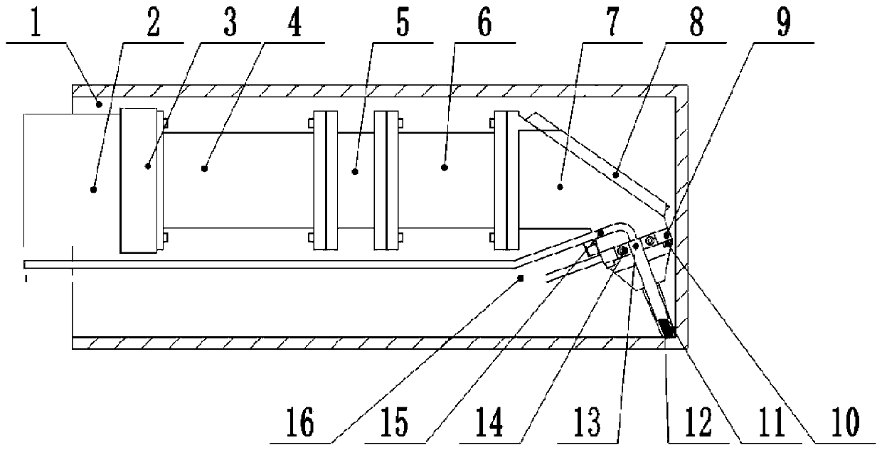
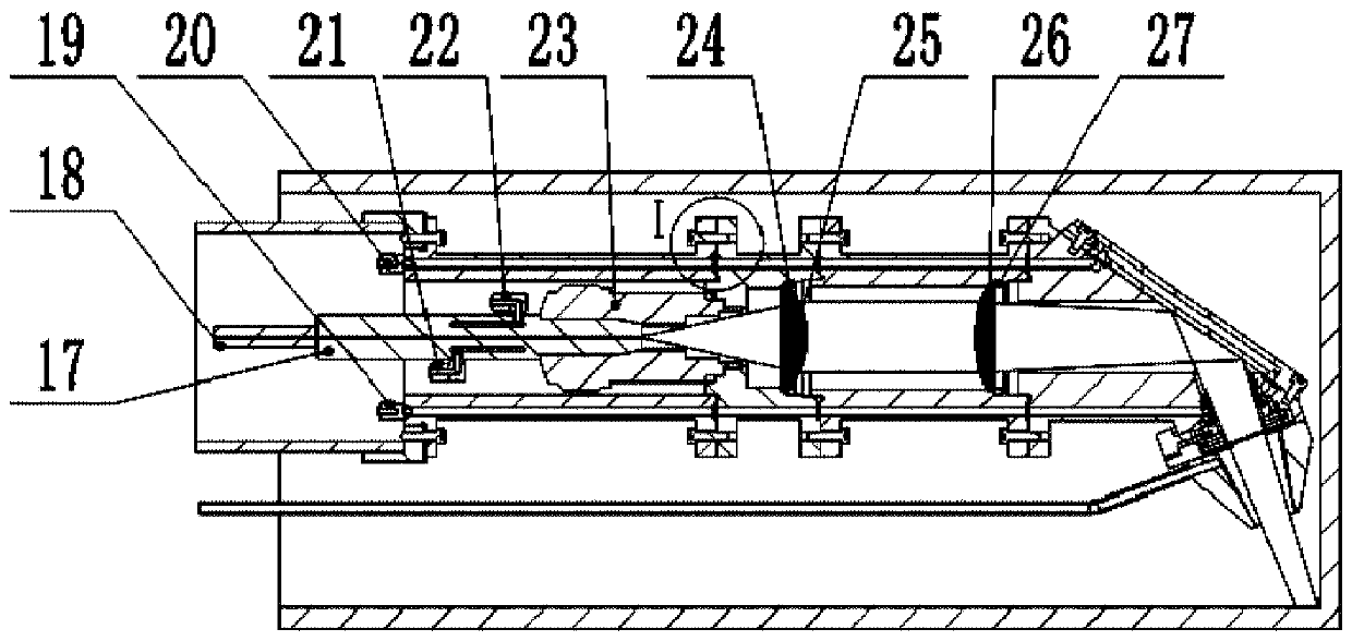
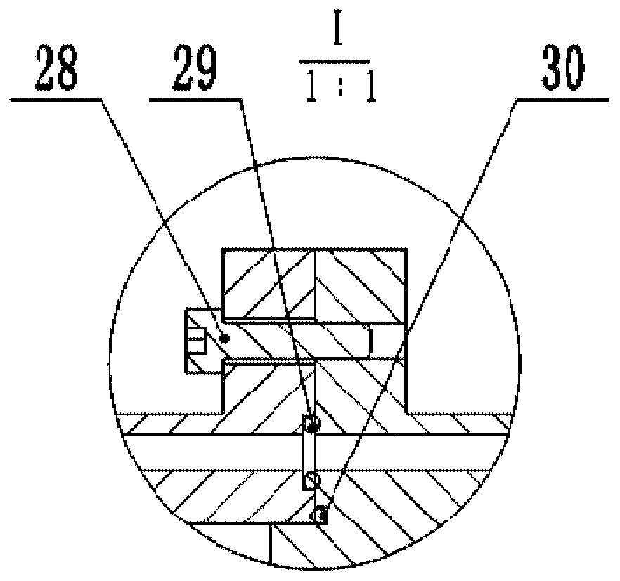
[0030] The present invention proposes a wide spot deep hole laser cladding head, as attached Figure 1-3 As shown, the cladding head shown includes: connecting pipe 2, connecting end cap 3, interface cover 4, collimating mirror seat 5, focusing mirror seat 6, reflecting mirror seat 7, reflecting mirror 8, light shield 9, first Fixing screw 10, wide spot powder feeding head 13, second fixing screw 14, powder feeding tube 15, protective gas tube 16, optical fiber male connector 17, optical fiber 18, optical fiber female connector 23, collimating lens fixing ring 24, collimating lens 25 , Integral focusing lens 26, focusing lens fixing ring 27, third fixing screw 28, first sealing ring 29, second sealing ring 30, fou...


PUM


Abstract

The invention provides a wide light spot deep hole laser cladding head. The device comprises an interface outer cover, a collimating lens seat, a focusing lens seat, a reflecting mirror seat, a reflecting mirror, a light shield, a powder feeding head, a powder feeding pipe, a protection gas pipe, a collimating lens and an integral focusing lens, wherein the interface outer cover, the collimating lens seat and the focusing lens seat are sequentially connected; the reflecting mirror seat is provided with a light inlet end, a light reflecting end and a light emitting end; the focusing lens seat is connected with the light inlet end of the reflecting mirror seat; the reflecting mirror is installed at the light reflecting end of the reflecting mirror seat; the light shield is connected to the light emitting end of the reflecting mirror seat, the powder feeding head is installed on the light shield, the powder feeding pipe is connected to the powder feeding head, the protection gas pipe is connected to the light shield, the collimating lens is installed in the collimating lens seat, and the integral focusing lens is installed in the focusing lens seat. The wide light spot deep hole lasercladding head provided by the invention solves the development bottleneck problem of an existing deep hole laser cladding technology, and has the advantages of continuous and stable operation, high integration, small volume and wide popularization and application prospects.

Description

technical field [0001] The invention relates to the technical field of laser cladding, in particular to a wide-spot deep-hole laser cladding head. Background technique [0002] Corrosion of parts is the main cause of damage to mechanical equipment. The quality of anti-corrosion ability of parts is directly related to the safe operation of mechanical equipment. It is a recently developed anti-corrosion technology to clad alloy powder on the inner wall of deep-hole workpieces by laser, but The existing laser cladding technology generally has problems such as low cladding efficiency, large cladding head volume, and poor adaptability to the high temperature environment of the inner hole, especially for the laser cladding problem on the inner wall of the deep hole workpiece, the existing laser cladding head cannot The cladding reaches the root of the deep hole workpiece, and cannot meet the cladding requirements of long-term operation. Looking at the existing laser cladding heads...

Claims


Application Information

Patent Timeline
Patent Type & Authority Applications(China)
IPC IPC(8): C23C24/10
CPCC23C24/103
Inventor 李建勋苏成明曹鹏张毅张飘飘
Owner SHAANXI TIANYUAN MATERIALS PROTECTION TECH
Why Eureka
Try Eureka