
Polyester staple fiber post-processing production equipment and process thereof

A technology of polyester staple fiber and production equipment, which is applied in the field of polyester staple fiber post-processing production equipment and its technology, can solve the problems of inability to guarantee the spraying of short fibers, affect product quality, generate static electricity, etc., and achieve a simple and ingenious structure and low cost. , the effect of improving quality

Inactive Publication Date: 2019-11-15
浙江时代纤维有限公司
View PDF1 Cites 1 Cited by
  • Summary
  • Abstract
  • Description
  • Claims
  • Application Information

AI Technical Summary

Problems solved by technology

[0005] One of the purposes of the present invention is to address the deficiencies of the prior art, to provide a polyester staple fiber post-processing production equipment, which is conveyed through the first conveyor belt and the second conveyor belt, one high and one low, and a The shaking device, the short fiber is shaken by the shaking mechanism under the drive of the rotating mechanism, and the antistatic agent is sprayed on the short fiber during the shaking, which solves the problem of spraying the antistatic agent in the existing way. The uniformity of the coating is poor, and it is impossible to ensure that the short fibers on the surface and the bottom can be sprayed, so that the short fibers at the bottom will still generate static electricity during the subsequent processing process, which affects the technical problems of product quality.

Method used


Image

  • Polyester staple fiber post-processing production equipment and process thereof
  • Polyester staple fiber post-processing production equipment and process thereof
  • Polyester staple fiber post-processing production equipment and process thereof

Examples


Embodiment 1

[0048] Embodiments of the present invention are described in detail below, examples of which are shown in the drawings, wherein the same or similar reference numerals designate the same or similar elements or elements having the same or similar functions throughout. The embodiments described below by referring to the figures are exemplary and are intended to explain the present invention and should not be construed as limiting the present invention.

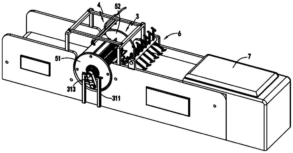
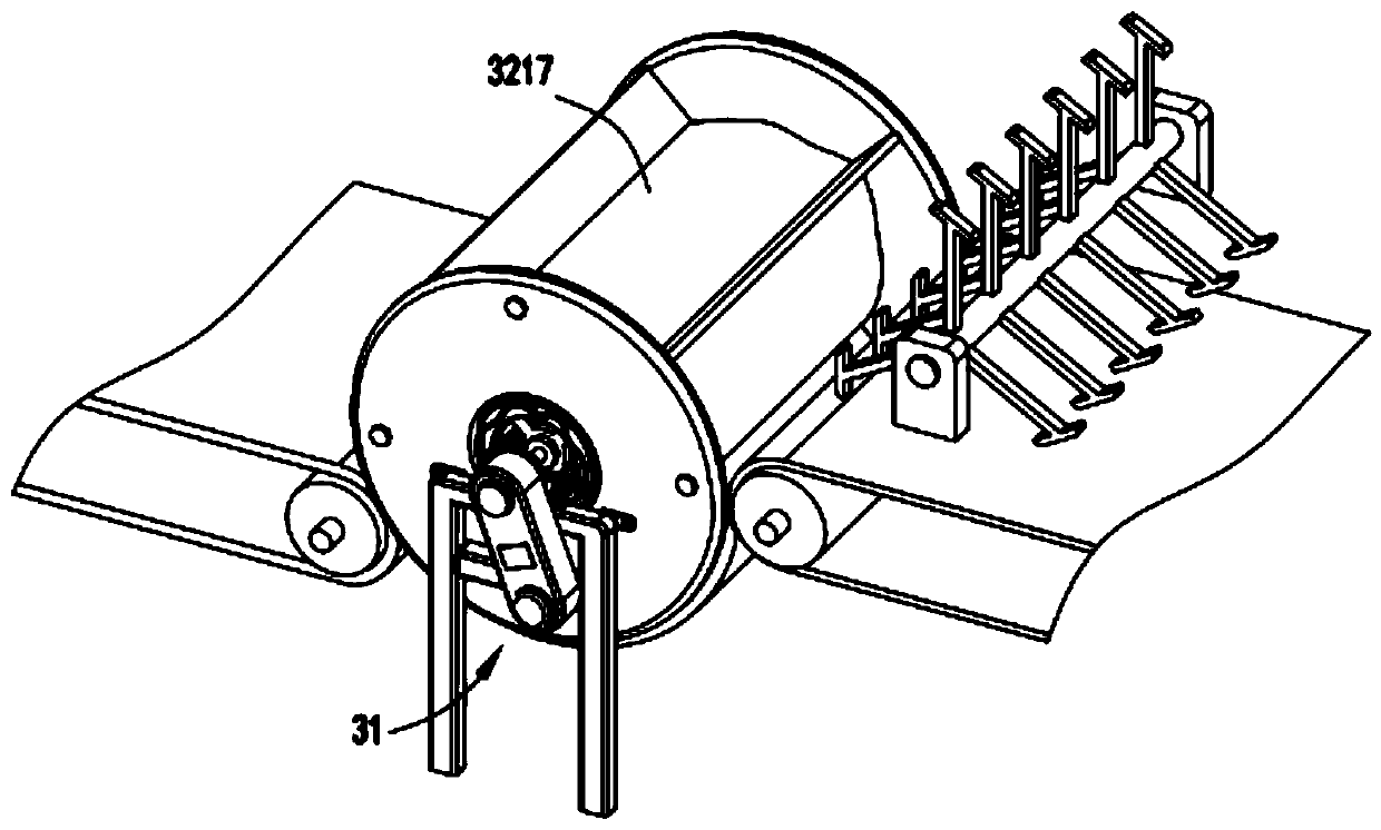
[0049] Such as Figure 1 to Figure 9 As shown, a polyester staple fiber post-processing production equipment includes a first conveyor belt 1 and a second conveyor belt 2 arranged front and back, and a shaking device 3 is arranged between the first conveyor belt 1 and the second conveyor belt 2 , the top of the shaking device 3 is provided with a spraying device 4, the shaking device 3 includes a rotating mechanism 31 and a shaking mechanism 32, and the shaking mechanism 32 accepts the short fibers transported by the first convey...

Embodiment 2

[0064] Such as image 3 As shown, the parts that are the same as or corresponding to those in Embodiment 1 adopt the reference numerals corresponding to Embodiment 1. For the sake of simplicity, only the differences between Embodiment 1 and Embodiment 1 are described below; the differences between Embodiment 2 and Embodiment 1 The difference is that: further, a shifting mechanism 6 is provided at the tail end of the first conveyor belt 1, and the shifting mechanism 6 includes a rotating shaft 61 that rotates in the clockwise direction and is arranged in an array along the length direction of the rotating shaft 61. There are several shifting rods 62, the ends of the shifting rods 62 are provided with inclined shifting feet 63.

[0065] In this embodiment, the short fibers before entering the turning device are preliminarily dispersed by setting the material shifting mechanism 6. The combination of the two makes the effect of the subsequent turning device better when the short f...

Embodiment 3

[0067] Such as Figure 10 as shown,

[0068] A post-treatment production process for polyester staple fibers, comprising the following production steps:

[0069] Step 1, the transmission and drying process, the short fibers are transported through the oven under the drive of the first transmission belt 1 for drying treatment;

[0070] Step 2, the feeding process, the dried short fibers are transferred to the feeding station, and the feeding mechanism 6 located at the feeding station distributes the short fibers in the transmission process backward;

[0071] Step 3, the shaking process, the short fiber distributed in the step 2 enters the shaking station, and the rotating mechanism 31 located at the turning station drives the short fiber to rotate, and the shaking mechanism passes through the shaking mechanism during the rotation. 32 shake short fibers;

[0072] Step 4, spraying process, the staple fibers in the step 3 are in the process of shaking, the spraying device 4 abo...


PUM


Abstract

The invention relates to the field of staple fiber production equipment, in particular to polyester staple fiber post-processing production equipment. The equipment comprises a first conveyor belt anda second conveyor belt which are arranged front and rear, a turnover and shaking device is arranged between the first conveyor belt and the second conveyor belt, and a spraying device is arranged above the turnover and shaking device; the turnover and shaking device comprises a rotating mechanism and a shaking mechanism, the shaking mechanism receives staple fibers conveyed by the first conveyorbelt and is driven by the rotating mechanism to support the staple fibers to rotate, the staple fibers are turned over, shaken and scattered by the shaking mechanism in the rotation process, and the spraying device cooperates with the shaking mechanism to spray an anti-static agent to the staple fibers which are continuously turned over and shaken. The invention further provides a corresponding production process. The technical problems are solved that existing anti-static agent spraying modes are poor in spraying uniformity, it cannot be ensured that an anti-static agent is sprayed to staplefibers at the surface layer and the bottom, the staple fibers at the bottom can still generate static electricity in the subsequent treatment process, and the product quality is influenced.

Description

technical field [0001] The invention relates to the technical field of polyester staple fiber post-processing equipment, in particular to a polyester staple fiber post-processing production equipment and a process thereof. Background technique [0002] Polyester staple cotton is prone to static electricity during the production process, and it is necessary to spray antistatic liquid on the staple cotton. In the existing processing flow, a manual hand-held spray gun is used to spray antistatic agent on the output short-fiber cotton. The problem with this processing method is that it will consume a large labor cost, and the manual operation will inevitably lead to the problem of missing antistatic agent or uneven spraying of antistatic agent. Therefore, how to develop a new type of non-woven fabric opening and blending production equipment that can overcome the above problems is a direction that those skilled in the art need to study. [0003] The Chinese utility model paten...

Claims


Application Information

Patent Timeline
IPC IPC(8): D01G9/00D01G9/14D01G9/16D06B1/02
CPCD01G9/00D01G9/14D01G9/16D06B1/02
Inventor 徐卫东
Owner 浙江时代纤维有限公司
Learn More