
Heating terminal machine

A technology of terminals and racks, which can be used in household heating, space heating and ventilation details, heating methods, etc. It can solve the problems of low electrothermal conversion efficiency, inconvenient use, uncontrollable temperature, etc. Efficiency improvement and rapid heating effect

Pending Publication Date: 2019-11-15
山东鬼谷环保科技有限公司
View PDF0 Cites 1 Cited by
  • Summary
  • Abstract
  • Description
  • Claims
  • Application Information

AI Technical Summary

Problems solved by technology

[0002] In half of our country, the temperature stays below zero for a long time in winter, and indoor heating is required to ensure normal life. Cities usually use central heating, but this method relies on coal combustion to heat boilers, which pollutes the air, and new rural areas do not It is suitable for connecting to the central heating pipe network, so some heating terminals use electric heating tubes for heating. However, the traditional electric heating tubes have low effective electrothermal conversion efficiency, the weight of the whole machine is large, it is inconvenient to use, the temperature rises slowly, and the temperature is not stable. control, it is easy to cause serious consequences such as fire

Method used


Image

  • Heating terminal machine
  • Heating terminal machine
  • Heating terminal machine

Examples

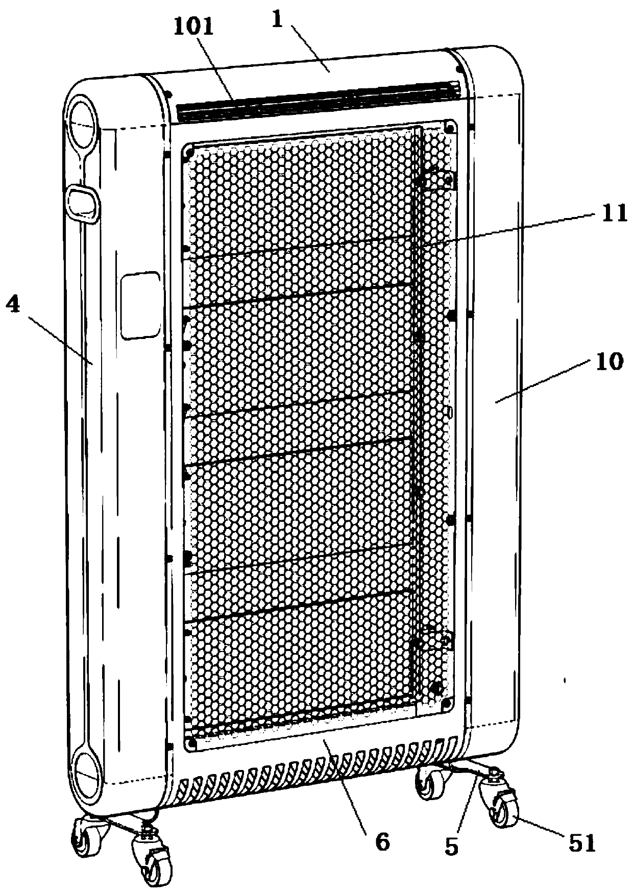
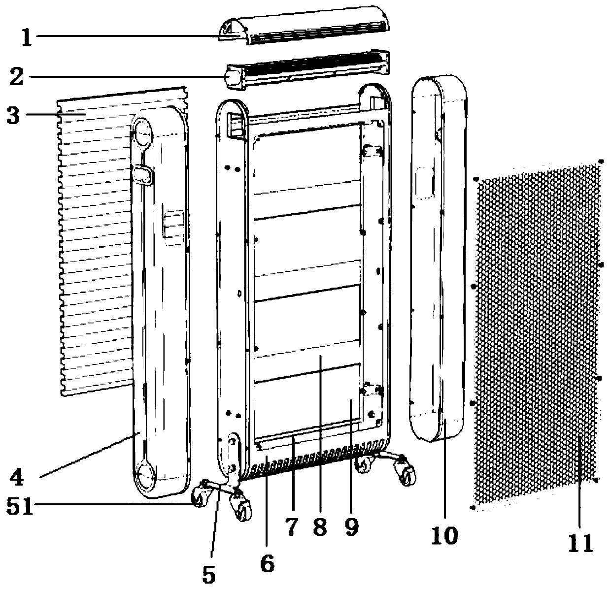
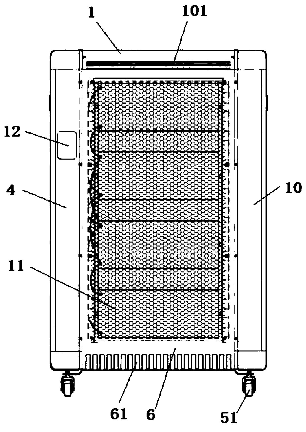

Embodiment Construction

[0026] The present invention is described in further detail now in conjunction with accompanying drawing.

[0027] Such as Figure 1-9 The heating terminal machine shown includes a frame shell 6, a left frame shield 4, a right frame shield 10, and an upper air outlet mask 1, and ten thousand to the wheel support frame, at least two universal wheels are installed under the universal wheel support frame, a heating plate fixing frame 7 is arranged in the middle of the frame housing 6, and a plurality of Heating plate monomer 9, isolating plate 8 is arranged between two adjacent heating plate monomers 9, the front side of described frame housing 6 is equipped with protective grid 11, the rear side of frame housing 6 A heat conduction heating plate 3 is installed, a cross-flow fan 2 is installed on the upper end of the frame casing 6, a left frame shield 4 is installed on the left side of the frame casing 6, and a left frame shield 4 is installed on the right side of the frame cas...


PUM


Abstract

The invention relates to a heating terminal machine. The heating terminal machine comprises a machine frame shell, a left machine frame shield, a right machine frame shieldand an upper air outlet cover, a heating plate fixing frame is arranged in the middle of the machine frame shell, a plurality of heating plate bodies are fixedly arranged in the heating plate fixing frame, an isolation plate isarranged between every two adjacent heating plate bodies, a protective grid network is arranged on the front side surface of the machine frame shell, a heat conduction heating plate is arranged on therear side surface of the machine frame shell, a cross-flow fan is arranged at the upper end of the machine frame shell, the left machine frame shield is arranged on the left side of the machine frameshell, the right machine frame shield is arranged on the right side of the machine frame shell, and the upper air outlet cover is buckled at the upper end of the machine frame shell. The heating terminal machine has the advantages that three modes of radiation, convection and conduction are adopted to release heat load to a heating space, the process is controlled by a preset intelligent temperature control unit, an intermittent heating linkage energy-saving operation mode is adopted, when the safety is ensured, the energy consumption is fast, the service life is long, and the designed service life can reach 25000 hours.

Description

technical field [0001] The invention relates to the technical field of heating equipment, in particular to a heating terminal. Background technique [0002] In half of our country, the temperature stays below zero for a long time in winter, and indoor heating is required to ensure normal life. Cities usually use central heating, but this method relies on coal combustion to heat boilers, which pollutes the air, and new rural areas do not It is suitable for connecting to the central heating pipe network, so some heating terminals use electric heating tubes for heating. However, the traditional electric heating tubes have low effective electrothermal conversion efficiency, the weight of the whole machine is large, it is inconvenient to use, the temperature rises slowly, and the temperature is not stable. control, it is easy to cause serious consequences such as fire. Contents of the invention [0003] In order to overcome the above disadvantages, the object of the present in...

Claims


Application Information

Patent Timeline
Patent Type & Authority Applications(China)
IPC IPC(8): F24D13/00F24D19/02F24D19/00
CPCF24D13/00F24D19/00F24D19/0203
Inventor 李涌泉刘鹏
Owner 山东鬼谷环保科技有限公司
Learn More