Trajectory tracking control methods and trajectory tracking systems

A control method and trajectory tracking technology, applied in general control systems, control/regulation systems, digital control, etc., can solve problems such as no trajectory tracking system, large trajectory tracking error, and inability to complete the trajectory tracking purpose

Active Publication Date: 2019-11-15
SUZHOU RUINIU ROBOT TECH CO LTD
View PDF12 Cites 3 Cited by
  • Summary
  • Abstract
  • Description
  • Claims
  • Application Information

AI Technical Summary

Problems solved by technology

This method is based on the track deviation information detected by the sensor. If it is unbiased and not corrected, then even if there is no deviation in the current position of the tool, after advancing according to the predetermined task track, the tool position will also deviate at the next moment, so the whole process cannot be realized theoretically. Unbiased tracking can only reduce the deviation to no more than the new deviation caused by each step forward, so the purpose of trajectory tracking can be better achieved only when the radius of curvature of the trajectory is large or the fluctuation of the trajectory is small, but If the radius of curvature of the trajectory is small or the fluctuation of the trajectory is large, the trajectory tracking will produce a large trajectory tracking error, and even the purpose of trajectory tracking cannot be achieved.
At present, it is cumbersome to set up a tracking system, and for trajectories, especially space curve trajectories, there is no general trajectory tracking control method and a trajectory tracking system that implements the trajectory tracking control method.

Method used


Image

  • Trajectory tracking control methods and trajectory tracking systems
  • Trajectory tracking control methods and trajectory tracking systems
  • Trajectory tracking control methods and trajectory tracking systems

Examples


Embodiment 1

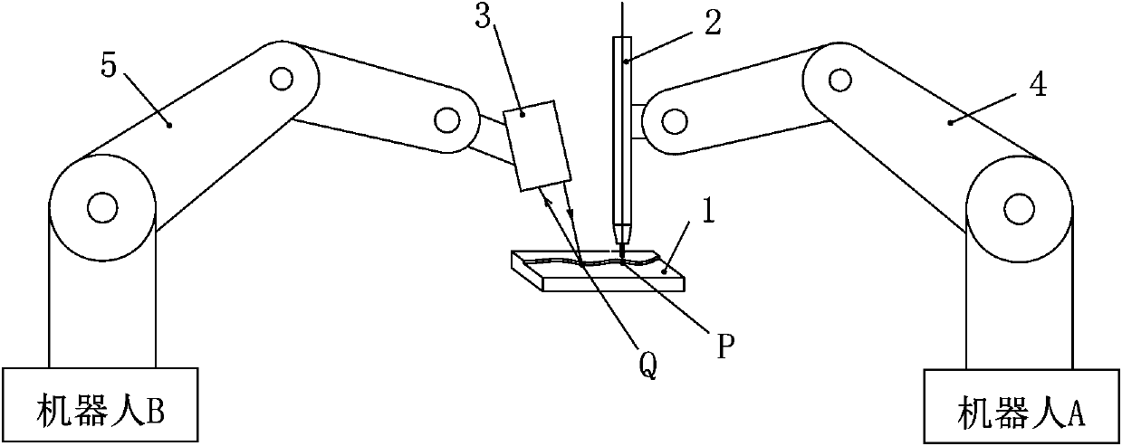
[0210] This trajectory tracking control method is used in situations where the sensor 3 and the tool 2 are respectively driven by different branch chains. see figure 1 As shown, there are two branch chains here: tool branch chain 4 and sensor branch chain 5, tool 2 is attached to tool branch chain 4 and tool 2 is driven by tool branch chain 4, sensor 3 is attached to sensor branch chain 5 and sensor 3 is driven by the sensor branch chain 5, and the relative position between the sensor 3 and the tool 2 has a definite geometric relationship. The sensor branch chain 5 and the tool branch chain 4 can be two branch chains on the same actuator, or a branch chain composed of two separate actuators. The forward speed at which the sensor branch chain 5 drives the sensor 3 can be the same as that at which the tool branch chain 4 drives the tool 2 forward, that is, the sensor 3 and the tool 2 can advance at the same forward speed. The forward speed and the forward speed of the tool bra...

Embodiment 2

[0277] The difference between this embodiment and Embodiment 1 is that this embodiment is based on the reference point Ref-A, and instead of using the above-mentioned current control reference point Ref-A as the tracking target, it uses the control interval time t The subsequent control reference point Ref-A-next is the tracking target. In this embodiment, the specific determination method of determining the target position of tool 2 at the next moment according to the trajectory position information set {Q} is as follows:

[0278] Take the reference point Ref-A as the center of the sphere, and make a sphere with △=V*t as the radius. There are two intersection points between the sphere and the trajectory feature line, and the intersection of the sphere and the trajectory feature line in the tool’s forward direction is taken as the control reference point Ref-A-next, with the control reference point Ref-A-next as the tracking target, determine the tool coordinate system at the ...

Embodiment 3

[0283] The difference between this embodiment and Embodiment 1 is that in this embodiment, in the fourth step of determining the target, the position and posture of the detection point of the sensor at the next moment are determined according to the trajectory position information set {Q}, and the position of the detection point of the tool at the next moment is determined. On the basis of the target position and attitude of the sensor, the first position and attitude deviation information between the position of the sensor detection point at the current moment and the position of the sensor detection point at the next moment, the target position of the tool at the current moment and the position of the tool at the next moment Regarding the second position and attitude deviation information between the target positions, the other steps of the trajectory tracking control method and the specific development of each step are the same as those in Embodiment 1, and will not be repeat...


PUM


Abstract

The invention discloses four trajectory tracking control methods and corresponding trajectory tracking systems. The four trajectory tracking control methods are consistent in basic ideas. Concretely,trajectory information which is described by a sensor coordinate system and obtained by the sensor is fixed, namely, the information is transformed to the form that is suitable for integrated description of the coordinate system of the trajectory information for marking, the real trajectory is presented gradually, basis is provided for subsequent target resolution, an ideal state that should be presented by a tool at present time or state that needs to be achieved in next correction time after correction of present time is found according to a target, and the trajectory of the tool is corrected by driving an executor according to the above information. Thus, errors caused by advancing of detection points are overcome, independent operation independent demonstration information is achieved,the positional error as well as the attitude error of the tool can be corrected, and a trajectory tracking effect is good.

Description

technical field [0001] The invention relates to the technical field of trajectory automatic tracking, in particular to a trajectory tracking control method in which a sensor is driven by a sensor branch chain and a tool is driven by a tool branch chain, and a trajectory tracking system for realizing the trajectory tracking control method. Background technique [0002] Welding, gluing, cutting and other operations are similar routine operations, and their common feature is to operate along a specific trajectory. If the specific trajectory position can be detected by sensors, the trajectory can be adjusted by robots and other actuators. Tracking to automate jobs. [0003] Advanced ones in existing trajectory tracking systems use sensors to track trajectories, for example, arc welding robot systems use structured light vision sensors to track trajectories. The actuator in the trajectory tracking system itself has a task trajectory predetermined by means of teaching information...

Claims


Application Information

Patent Timeline
Patent Type & Authority Applications(China)
IPC IPC(8): G05B19/19
CPCG05B19/19G05B2219/31443
Inventor 吕伟新熊斌张启航王磊郭振杰
Owner SUZHOU RUINIU ROBOT TECH CO LTD
Why Eureka
Try Eureka