

Phase noise compensation device and method and receiver
A phase noise compensation and phase noise technology, applied in the fields of receivers, phase noise compensation devices and methods, can solve problems such as phase noise sensitivity, achieve the effects of accurately estimating phase noise and ensuring transmission efficiency and performance
- Summary
- Abstract
- Description
- Claims
- Application Information
AI Technical Summary
Problems solved by technology
Method used
Image

Examples
Embodiment 1
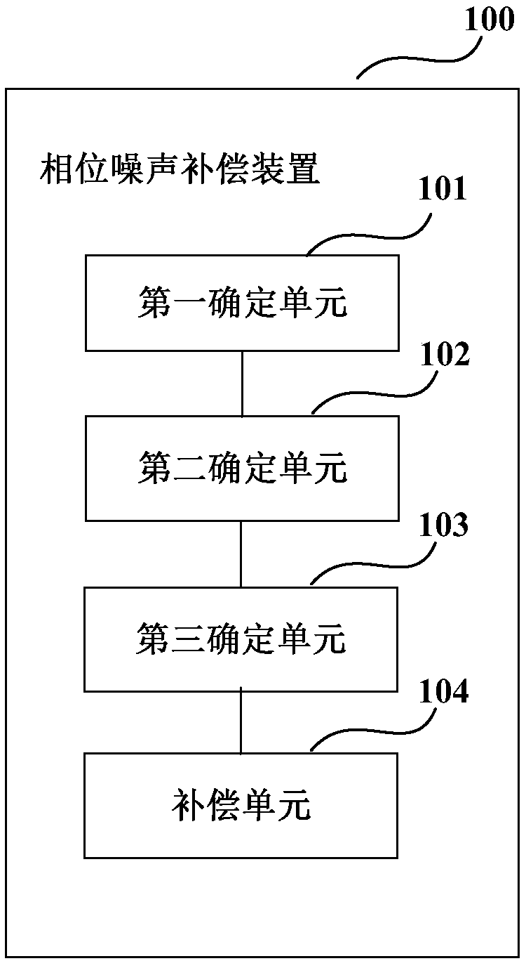
[0025] An embodiment of the present invention provides a phase noise compensation device, and the phase noise compensation device is arranged at a receiver end of an optical communication system. figure 1 is a schematic diagram of the phase noise compensation device according to Embodiment 1 of the present invention. Such as figure 1 As shown, the device 100 includes:
[0026] A first determination unit 101, configured to determine an estimated value of an unideal parameter of a transmitter according to a received signal;
[0027] The second determination unit 102 is configured to determine the correction signal according to the estimated value of the unideal parameter of the transmitter and the training sequence signal inserted into the transmission signal of the transmitter;
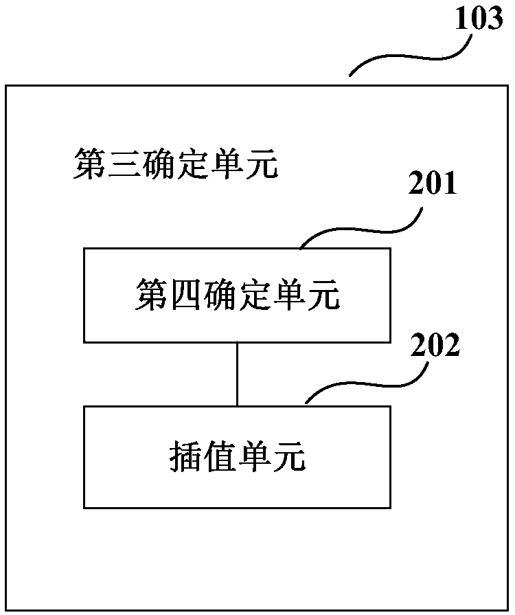
[0028] A third determining unit 103, configured to determine the phase noise of the received signal according to the modified signal; and
[0029] The compensation unit 104 is configured to perform ...
Embodiment 2
[0070] An embodiment of the present invention also provides a receiver, which includes the phase noise compensation device according to Embodiment 1. The specific structure and functions of the phase noise compensation device can refer to the description in Embodiment 1, and will not be repeated here. .
[0071] Figure 5 It is a schematic block diagram of the system configuration of the receiver according to Embodiment 2 of the present invention. Such as Figure 5 As shown, the receiver 500 includes: an equalization unit 501, a frequency offset compensation unit 502, a phase noise compensation unit 503, a transmitter imperfect compensation unit 504, a first determination unit 505, a second determination unit 506, a third determination unit 507 and A bit error rate calculation unit 508 .
[0072] In this embodiment, the specific structures and functions of the equalization unit 501 , the frequency offset compensation unit 502 , the transmitter imperfect compensation unit 50...
Embodiment 3
[0078] An embodiment of the present invention also provides a phase noise compensation method, which corresponds to the phase noise compensation device in Embodiment 1.
[0079] Figure 6 is a schematic diagram of a phase noise compensation method according to Embodiment 3 of the present invention. Such as Figure 6 As shown, the method includes:
[0080] Step 601: Determine the estimated value of the unideal parameter of the transmitter according to the received signal;
[0081] Step 602: Determine the correction signal according to the estimated value of the unideal parameter of the transmitter and the training sequence signal inserted into the transmitted signal of the transmitter;
[0082] Step 603: Determine the phase noise of the received signal according to the modified signal; and
[0083] Step 604: Perform phase noise compensation on the received signal according to the phase noise of the received signal.
[0084] Figure 7 is another schematic diagram of the ph...
PUM
 Abstract
Description
Claims
Application Information