
Directly-connected mixed flow fan

A mixed-flow fan and fan technology, which is applied in the direction of mechanical equipment, machine/engine, liquid fuel engine, etc., can solve problems such as unstable work, and achieve the effects of light weight, low operating noise, and equipment protection

Inactive Publication Date: 2019-11-19
李诚
View PDF8 Cites 3 Cited by
  • Summary
  • Abstract
  • Description
  • Claims
  • Application Information

AI Technical Summary

Problems solved by technology

[0006] Aiming at the deficiencies of the prior art, the present invention provides a direct-connected mixed-flow fan, which is equipped with lifting parts to make the lifting more convenient, which makes the installation convenient, the air flow efficiency is high during operation, and it is energy-saving and low-noise, and solves the problem of the motor Direct connection makes the work unstable, and it can also protect the equipment well and prevent equipment damage, which is extremely practical
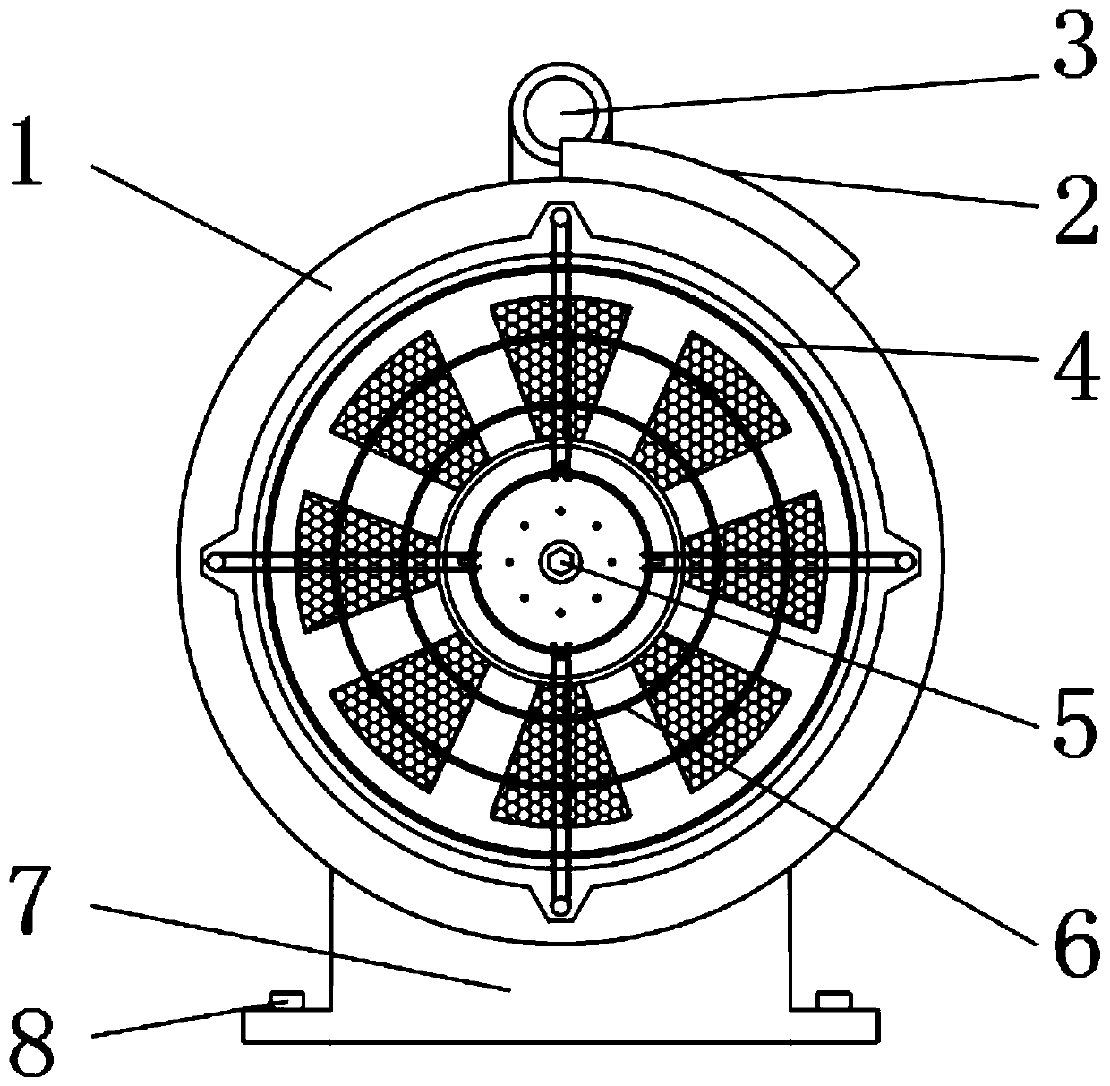
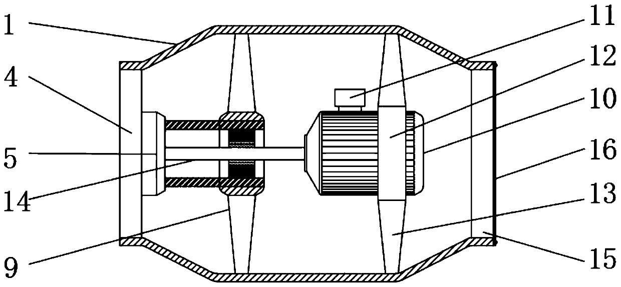
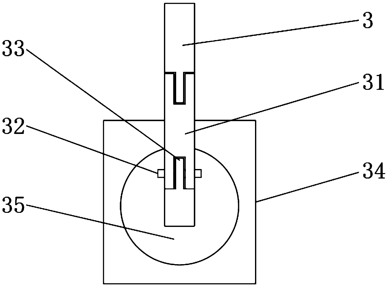
[0008] In order to achieve the above-mentioned purposes of easy installation, high airflow efficiency during work, energy saving and low noise, and solve the problem of unstable work caused by direct connection of motors, and can also protect equipment well and prevent equipment damage, the present invention The following technical solution is provided: a direct-connected mixed-flow fan, including a fan casing, a fan junction box is arranged on the upper outer surface of the fan casing, and a lifting piece is arranged on the upper outer surface of the fan casing near the rear end of the fan junction box, The outer surface of the front end of the fan casing is provided with an air outlet, and the inner side of the fan casing is provided with a working part near the center of the air outlet. The outer surface of the front end of the air outlet is provided with a protective grid. The bottom of the fan casing The outer surface of the fan base is provided with a fan base, and the inner side of the upper end of the fan base is provided with hexagonal bolts;

Method used


Image

  • Directly-connected mixed flow fan
  • Directly-connected mixed flow fan
  • Directly-connected mixed flow fan

Examples


Embodiment Construction

[0031] The following will clearly and completely describe the technical solutions in the embodiments of the present invention with reference to the accompanying drawings in the embodiments of the present invention. Obviously, the described embodiments are only some, not all, embodiments of the present invention. Based on the embodiments of the present invention, all other embodiments obtained by persons of ordinary skill in the art without making creative efforts belong to the protection scope of the present invention.

[0032] see Figure 1-6 , a direct-connected mixed flow fan, comprising a fan casing 1, a fan junction box 2 is arranged on the upper outer surface of the fan casing 1, and a lifting member 3 is arranged on the upper outer surface of the fan casing 1 near the rear end of the fan junction box 2, and the fan casing The outer surface of the front end of 1 is provided with an air outlet 4, the inner side of the fan housing 1 is provided with a working part 5 near t...


PUM


Abstract

The invention relates to the technical field of fans and discloses a directly-connected mixed flow fan. The directly-connected mixed flow fan comprises a fan casing, wherein a fan junction box is arranged on the outer surface of the upper end of the fan casing; lifting pieces are arranged at positions, near the rear end of the fan junction box,on the outer surface of the upper end of the fan casing; an air outlet is formed in the outer surface of the front end of the fan casing; a working part is arranged at the position, near the center of the air outlet, on the inner side of the fan casing;protective grids are arranged on the outer surface of the front end of the air outlet; a fan base is arranged on the outer surface of the bottom end of the fan casing; and hexagon bolts are arranged on the inner side of the upper end of the fan base in a through manner. By means of the directly-connected mixed flow fan, lifting of the directly-connected mixed flow fan is relatively convenient, installation is very convenient and fast indirectly; carbon fiber is used for achieving energy saving, low noise and relatively-high efficiency; the problem of unstable operation caused by the direct connection of a motor is solved; equipment parts can be effectively protected to prevent blades from being damaged; and the using effect is relatively good.

Description

technical field [0001] The invention relates to the technical field of fan equipment, in particular to a direct-connected mixed-flow fan. Background technique [0002] The direct-coupled mixed-flow fan refers to a fan between the axial fan and the centrifugal fan, and has low noise, low energy consumption, and a kind of production fan that is easy to disassemble. The direct-connected mixed-flow fan drives the motor shaft through the drive motor to make the fan rotate with the working turntable and blades, thereby generating airflow inside the fan casing and blowing it out of the blower outlet. [0003] The main function of the direct-connected mixed-flow fan is to generate mixed airflow. The blades of the direct-connected mixed-flow fan are installed obliquely. The impeller of the mixed-flow fan makes the air move both centrifugally and axially. (Diagonal flow) fan, the wind pressure coefficient is higher than that of the axial flow fan, and the flow coefficient is larger ...

Claims


Application Information

Patent Timeline
Patent Type & Authority Applications(China)
IPC IPC(8): F04D25/08F04D29/00F04D29/059F04D29/056F04D29/26F04D29/02F04D29/70
CPCF04D25/08F04D29/002F04D29/023F04D29/0563F04D29/059F04D29/26F04D29/703
Inventor 李诚
Owner 李诚
Learn More