A laser profile sensor calibration system and method based on intersection points

A calibration system and calibration method technology, applied in the field of laser profile sensor calibration system, can solve the problems of low precision, difficulty in making physical calibration objects, poor efficiency and the like

Active Publication Date: 2021-05-18
SHANGHAI JIAOTONG UNIV
View PDF7 Cites 0 Cited by
  • Summary
  • Abstract
  • Description
  • Claims
  • Application Information

AI Technical Summary

Problems solved by technology

[0009] Aiming at the problems of low precision, poor efficiency, and difficulty in making physical calibration objects in the existing laser profile sensor calibration methods, the present invention proposes a laser profile sensor calibration system and method based on intersections, by setting two intersecting planes The calibration object uses the intersection of the straight lines formed by the line laser on two planes as the calibration space point, and uses the displacement method to calibrate the laser profile sensor

Method used


Image

  • A laser profile sensor calibration system and method based on intersection points
  • A laser profile sensor calibration system and method based on intersection points
  • A laser profile sensor calibration system and method based on intersection points

Examples


Embodiment Construction

[0040] The present invention will be described in detail below in conjunction with specific embodiments. The following examples will help those skilled in the art to further understand the present invention, but do not limit the present invention in any form. It should be noted that those skilled in the art can make several modifications and improvements without departing from the concept of the present invention. These all belong to the protection scope of the present invention.

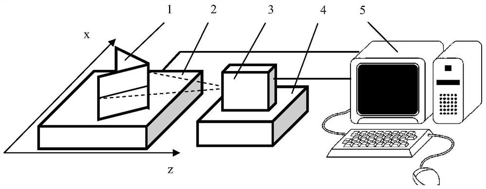
[0041] refer to figure 1 As shown, it is a schematic diagram of the composition of a laser profile sensor calibration system according to an embodiment of the present invention. The laser profile sensor calibration system includes a calibration object 1, a two-dimensional workbench 2, a laser profile sensor 3, a positioning mechanism 4, and a computer 5, wherein: the calibration object 1 is fixed on the two-dimensional worktable and can move with the two-dimensional worktable 1, the laser profile ...


PUM


Abstract

The present invention provides a laser profile sensor calibration system and method based on intersections, including: a calibration object, a two-dimensional worktable, a laser profile sensor, a positioning mechanism and a computer, and the calibration object is fixed on the two-dimensional workbench And can move with the two-dimensional workbench, the laser profile sensor is located on the positioning mechanism and fixed, the calibration object has two intersecting planes, and the intersection line of the two intersecting planes is facing the laser A profile sensor; the computer is connected to the two-dimensional workbench and the laser profile sensor. The calibration object of the present invention has two intersecting planes, and the intersection point of the straight line formed by the line laser on the two planes is used as a spatial point, and the displacement method is used to calibrate the laser profile sensor, which has the advantages of simple calibration object, easy manufacture, and calculation of spatial point coordinates With outstanding advantages such as high precision and no influence of deformation, it is suitable for any type of contour calibration.

Description

technical field [0001] The present invention relates to a calibration system and method in the field of measurement technology, in particular to a laser profile sensor calibration system and method based on intersection points. Background technique [0002] Contour measurement not only plays an important role in the industrial manufacturing process, but is also widely used in optical precision engineering, aerospace, robotics, chip manufacturing, automobile manufacturing, underwater detection and other fields, and has become a growing number of industrial applications. Function realization, equipment data acquisition, parts data acquisition, precision analysis, quality inspection and other essential links. [0003] With the increasing precision of manufacturing, non-contact contour measurement has gradually become the mainstream trend. Among them, the laser profile sensor based on the line structured light method has gradually become a hot spot. This method has outstanding...

Claims


Application Information

Patent Timeline
Patent Type & Authority Patents(China)
IPC IPC(8): G01B11/24
CPCG01B11/002G01B11/24
Inventor 赵辉陶卫吕娜崔斌冯宇孙昊南卓江刘凯媚
Owner SHANGHAI JIAOTONG UNIV
Why Eureka
Try Eureka