Electromagnet air gap limit adjusting device structure

An adjustment device and electromagnet technology, which is applied in the electromagnetic field, can solve the problems that the size of the air gap is not the best distance for the work, reduce the output torque of the electromagnet, and the size of the air gap is difficult to measure, etc., so that the gap adjustment is simple, convenient and accurate. The effect of reducing the speed of temperature rise and increasing the continuous use time

Pending Publication Date: 2019-11-19
JIANGXI LIANOVATION SUPERCONDUCTOR APPL CO LTD
View PDF0 Cites 0 Cited by
  • Summary
  • Abstract
  • Description
  • Claims
  • Application Information

AI Technical Summary

Problems solved by technology

[0003] First of all, the existing electromagnet air gap adjustment is usually adjusted through nuts or gaskets. On the one hand, the adjustment accuracy is limited, and the size of the air gap is not the best distance for the work, which reduces the output torque of the electromagnet and increases energy consumption. , on the other hand, with a long time, the adjustment accuracy of the nut or washer will further decrease, further reducing the performance of the electromagnet
[0004] Secondly, in order to increase the output power of the electromagnet, a yoke is usually provided outside the coil, and the yoke closes the magnetic field of the coil to improve the utilization rate of the magnetic field and then improve the attraction ability to the moving iron core. Due to the sealing effect of the yoke, It makes it difficult to measure the size of the internal air gap. On the one hand, because the electromagnet needs to use different air gaps in different occasions, because the air gap is not easy to measure, the air gap adjustment function is difficult to calibrate, and the reliability of the adjustment cannot be guaranteed. Especially when experimenting with the best air gap data in some occasions, on the other hand, after long-term use, the size of the internal air gap changes due to wear, deformation, and the decrease in the spring force of the reaction force, which reduces the efficiency of the electromagnet.

Method used


Image

  • Electromagnet air gap limit adjusting device structure
  • Electromagnet air gap limit adjusting device structure
  • Electromagnet air gap limit adjusting device structure

Examples


Embodiment Construction

[0022] The following will clearly and completely describe the technical solutions in the embodiments of the present invention with reference to the accompanying drawings in the embodiments of the present invention. Obviously, the described embodiments are only some, not all, embodiments of the present invention. Based on the embodiments of the present invention, all other embodiments obtained by persons of ordinary skill in the art without making creative efforts belong to the protection scope of the present invention.

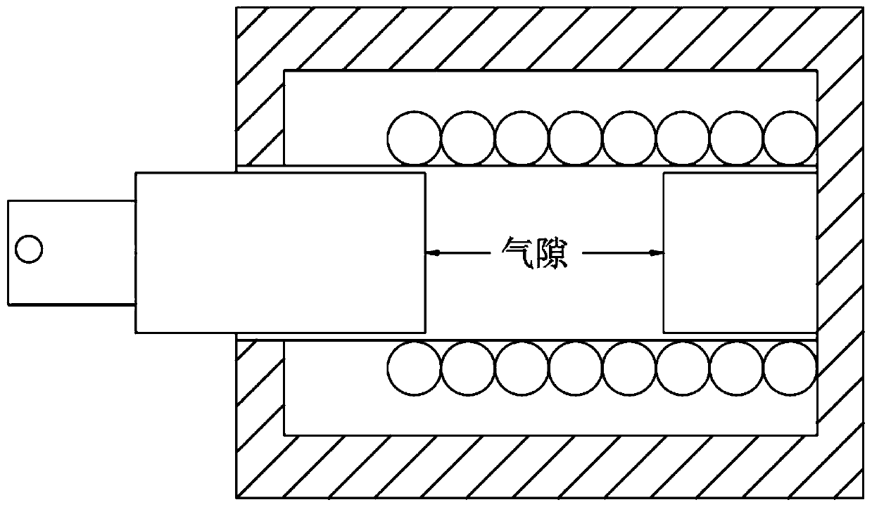
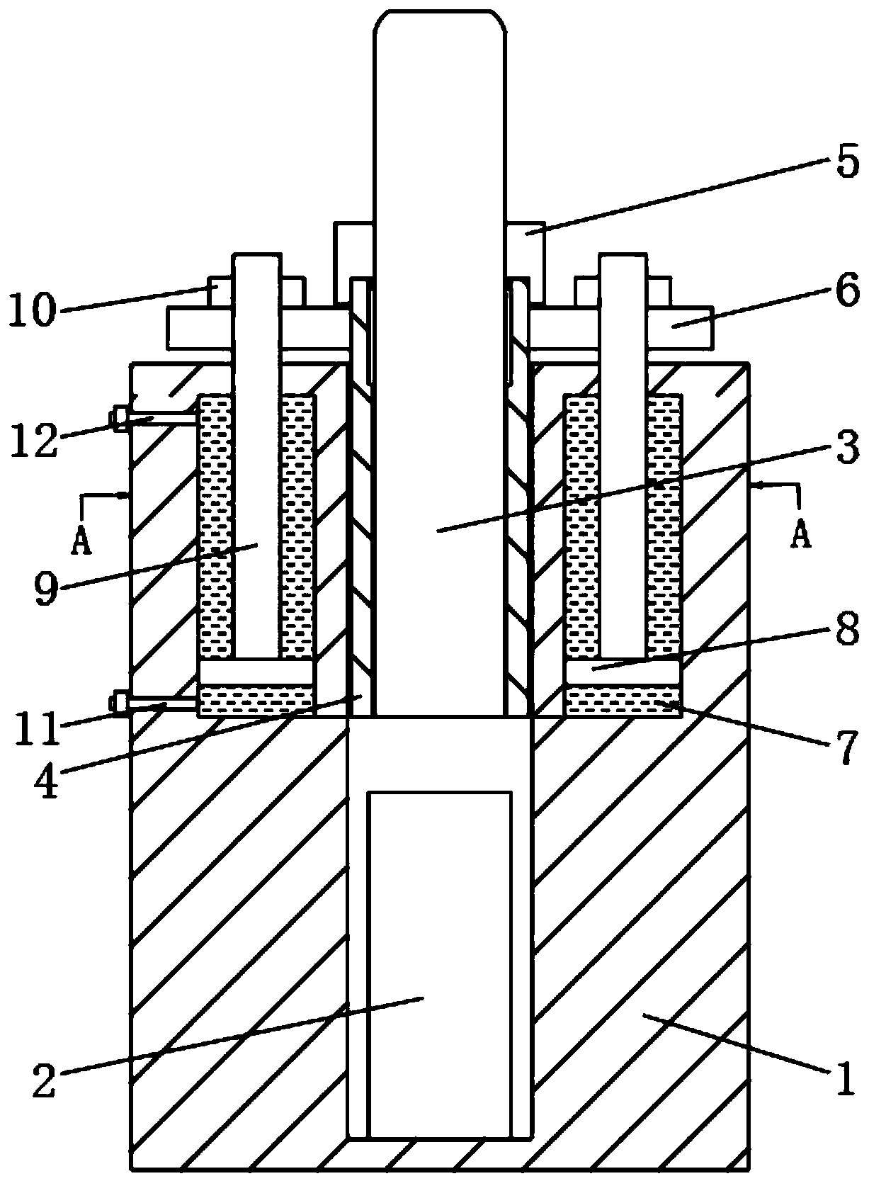
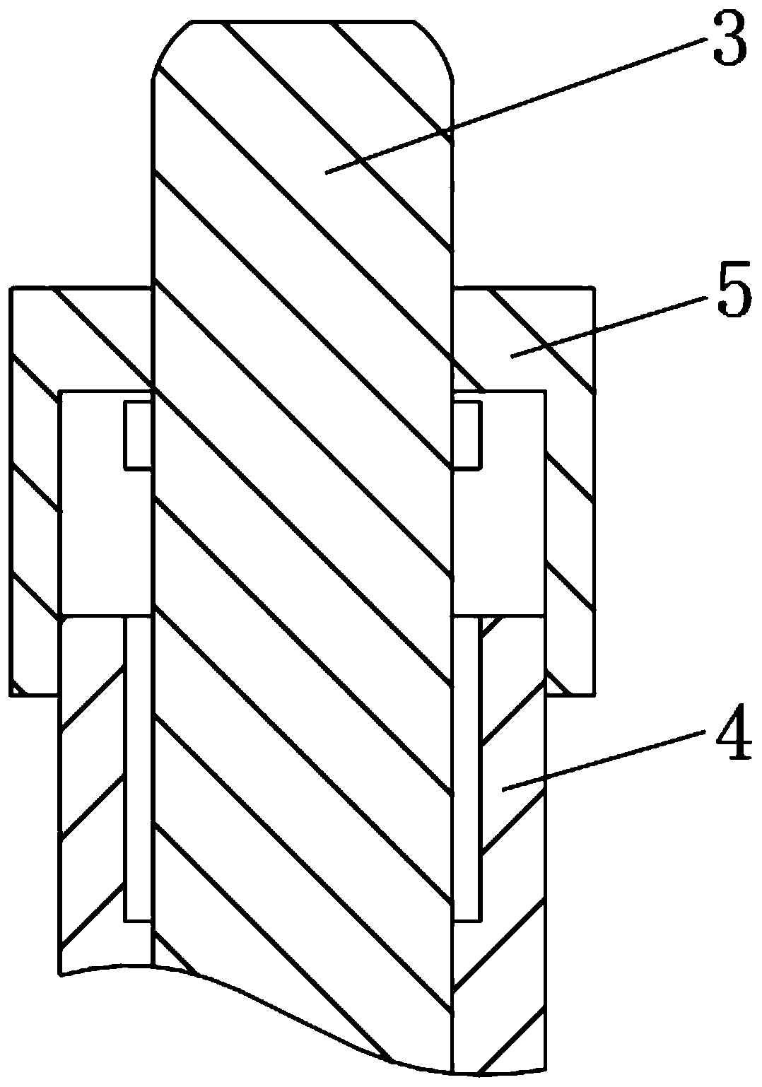
[0023] see Figure 1-5 , an electromagnet air gap limit adjustment device structure, including a housing 1, a static iron core 2 and an armature 3, the outer wall of the armature 3 is sleeved with an adjustment sleeve 4, and the housing 1 and the armature 3 are both connected to the adjustment sleeve 4 Mirror surface connection, the upper end of the outer wall of the adjustment sleeve 4 is connected with the adjustment disc 6, the adjustment disc 6 is rigidly ...


PUM


Abstract

The invention relates to the technical field of electromagnetic equipment, and discloses an electromagnet air gap limit adjusting device structure. The structure includes a shell, a static iron core and an armature; the outer sidewall of the armature is sleeved by an adjusting sleeve; and the upper end on the outer sidewall of the adjusting sleeve is connected to an adjusting disc. Through the structure, adjusted errors can be reduced by injecting hydraulic fluid to adjust an air gap of an electromagnet through a thin syringe, so that air gap adjusting precision can be ensured, and the errorsbrought by deformation can be eliminated; through the hydraulic fluid entering an adjusting hole and the hydraulic fluid extruded by a balancing hole, the rising distance of the adjusting sleeve and the change of the air gap are guaranteed to be uniform, so that actual air gap can be obtained by measuring any data, the accuracy of parameter setting can be guaranteed, and therefore, the accuracy ofthe optimum air gap data of experiments can be guaranteed; and as the hydraulic fluid is adopted to adjust the air gap and wraps the armature, effects of cooling the armature can be achieved.

Description

technical field [0001] The invention relates to the field of electromagnetic technology, in particular to a structure of an electromagnet air gap limit adjustment device. Background technique [0002] see figure 1 , the electromagnet gap is the movement stroke of the moving iron core in the electromagnet. The size of the air gap directly affects the normal operation of the feeder. Iron core collision will cause damage to the iron core and coil, so regular inspection and adjustment of the air gap is an important condition to ensure the normal operation of the electromagnet. [0003] First of all, the existing electromagnet air gap adjustment is usually adjusted through nuts or gaskets. On the one hand, the adjustment accuracy is limited, and the size of the air gap is not the best distance for the work, which reduces the output torque of the electromagnet and increases energy consumption. , On the other hand, over a long period of time, the adjustment accuracy of the nut or...

Claims


Application Information

Patent Timeline
Patent Type & Authority Applications(China)
IPC IPC(8): H01F7/121H01F7/16
CPCH01F7/121H01F7/1638
Inventor 蒋国忠黄建民李芳昕谭云海倪国华饶志文周呈劼吴启峰
Owner JIANGXI LIANOVATION SUPERCONDUCTOR APPL CO LTD
Why Eureka
Try Eureka