
Intramedullary positioning rod for improving precision of distal femoral osteotomy

An accurate, positioning rod technology, applied in the field of intramedullary positioning rods, can solve problems such as positioning rod positioning inaccuracy, and achieve the effect of increasing satisfaction

Inactive Publication Date: 2019-11-22
XUZHOU MEDICAL UNIV +1
View PDF4 Cites 0 Cited by
  • Summary
  • Abstract
  • Description
  • Claims
  • Application Information

AI Technical Summary

Problems solved by technology

[0005] The intramedullary positioning osteotomy of the distal femur is determined by measuring the angle between the mechanical axis and the anatomical axis before operation, and using the intramedullary positioning rod during the operation. Due to the differences in the anatomical shape of the femoral medullary cavity, the current positioning rod has inaccurate positioning Therefore, in view of the above status quo, it is urgent to develop an intramedullary positioning rod to improve the accuracy of distal femoral osteotomy, so as to overcome the shortcomings in the current practical application.

Method used


Image

  • Intramedullary positioning rod for improving precision of distal femoral osteotomy
  • Intramedullary positioning rod for improving precision of distal femoral osteotomy
  • Intramedullary positioning rod for improving precision of distal femoral osteotomy

Examples


Embodiment Construction

[0018] The technical solution of this patent will be further described in detail below in conjunction with specific embodiments.

[0019] Embodiments of the present patent are described in detail below, examples of which are shown in the drawings, wherein the same or similar reference numerals designate the same or similar elements or elements having the same or similar functions throughout. The embodiments described below by referring to the figures are exemplary and are only used for explaining the patent, and should not be construed as limiting the patent.

[0020] In the description of this patent, it is to be understood that the terms "center", "upper", "lower", "front", "rear", "left", "right", "vertical", "horizontal", The orientation or positional relationship indicated by "top", "bottom", "inner", "outer", etc. is based on the orientation or positional relationship shown in the drawings, and is only for the convenience of describing this patent and simplifying the des...


PUM


Abstract

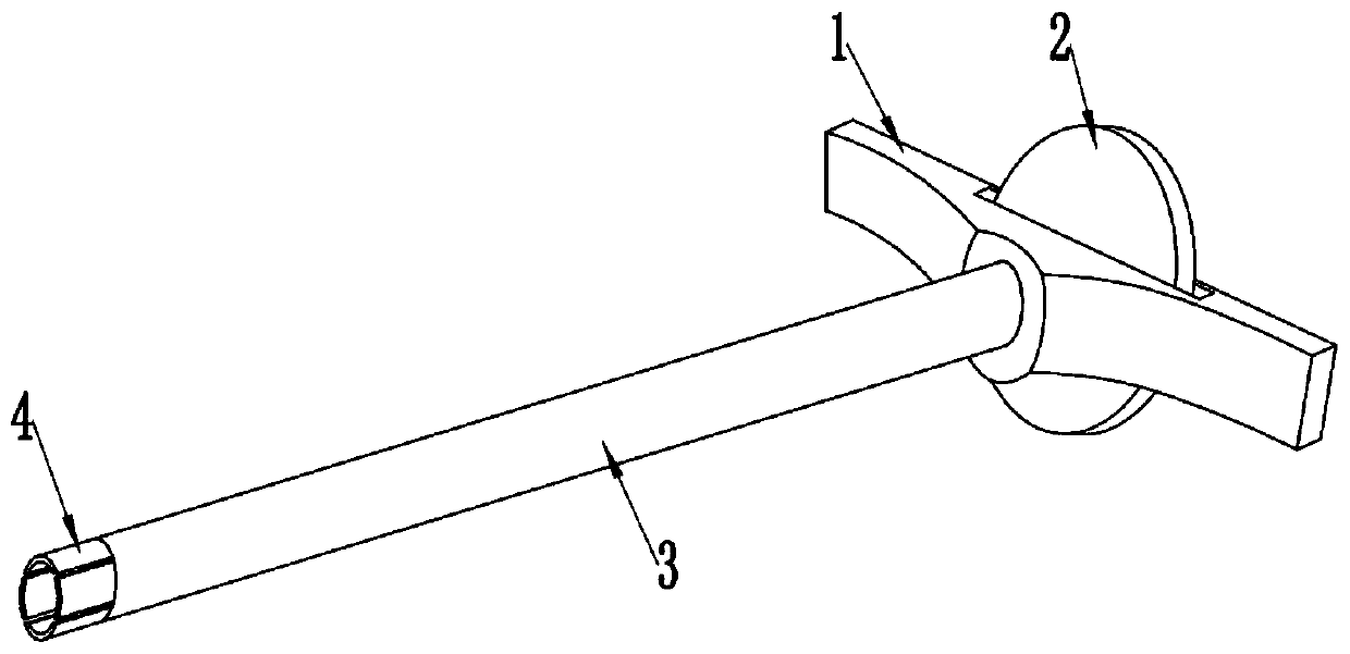
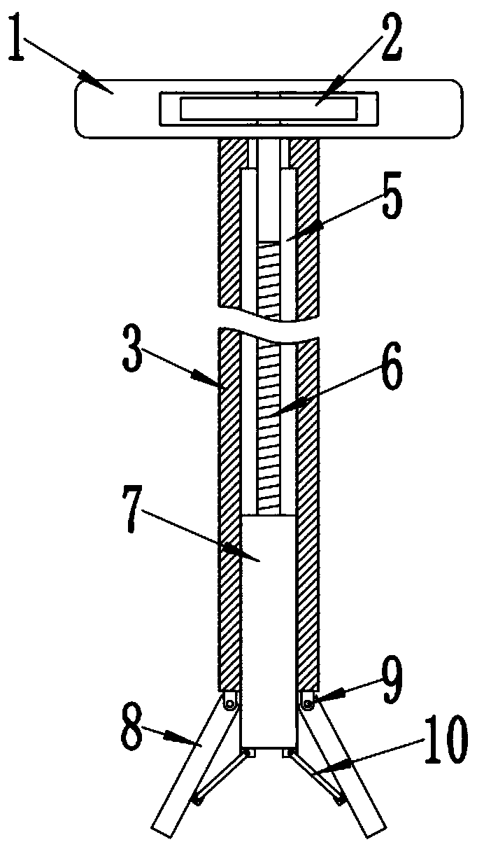
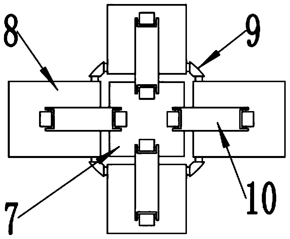
The invention relates to the technical field of clinical operation of knee joint replacement distal femoral osteotomy, in particular to an intramedullary positioning rod for improving the precision ofdistal femoral osteotomy. The intramedullary positioning rod for improving the precision of distal femoral osteotomy includes a handle, a straight rod and a positioning head; one end of the straightrod is fixedly connected with the lower part of the handle, and the other end of the straight rod is provided with the positioning head; a sliding groove is formed in the interior of the straight rod,a screw is rotatably installed inside the sliding groove, a screw sleeve is threadedly connected with the lower part of the screw, a plurality of positioning pieces are symmetrically arranged at theopening of the straight rod, hinge bases, respectively located between two positioning pieces, are fixedly arranged on the straight rod, and the positioning pieces are hinged to the hinge bases; connecting rods are hinged to the inner sides of the positioning pieces, and the other ends of the connecting rods are hinged to the bottom of the screw sleeve. According to the intramedullary positioningrod for improving the precision of distal femoral osteotomy, by adding a rotary table to a handle end to control the tail end of the positioning rod, the tail end can be freely divided into four partsof the interior part, the exterior part, the back part and the front part, the position of the positioning rod in the femoral bone marrow cavity can be adjusted, it is ensured that the positioning rod can be precisely and effectively fixed to the center of the femoral bone marrow cavity, and accordingly the precision of distal femoral osteotomy and the postoperative satisfaction of a patient areimproved.

Description

technical field [0001] The invention relates to the technical field of clinical surgery for knee joint replacement distal femur osteotomy, in particular to an intramedullary positioning rod for improving the accuracy of distal femoral osteotomy. Background technique [0002] Coronal force line has always been a hot spot in total knee arthroplasty. To achieve the coronal neutral force line after total knee arthroplasty, the distal femur and proximal tibial osteotomies should be perpendicular to the mechanical axis of the femur and tibia respectively. osteotomy. The overlapping of tibial mechanical axis and anatomical axis can be achieved through extramedullary positioning, while the femoral mechanical axis is virtual. To achieve osteotomy perpendicular to the femoral mechanical axis, extramedullary positioning system and intramedullary positioning can be used in total knee arthroplasty. System, computer-aided navigation technology, CT / MRI-based patient-individualized osteoto...

Claims


Application Information

Patent Timeline
Patent Type & Authority Applications(China)
IPC IPC(8): A61B17/17A61B17/74
CPCA61B17/1732A61B17/1739A61B17/74
Inventor 徐石庄刘磊赵凤朝
Owner XUZHOU MEDICAL UNIV
Learn More