
Vibration method used for vibration handle

A handle and driver technology, which is applied to fluids, electromagnets, electromagnetic circuit devices that utilize vibration, etc., can solve the problems that operators tend to ignore handle feedback information, handle power consumption is large, and handle vibration is not obvious, etc., and achieve rich vibration. Signal feedback, long service life, and the effect of avoiding heating problems

Inactive Publication Date: 2019-11-22
江苏山河机电技术有限公司
View PDF5 Cites 0 Cited by
  • Summary
  • Abstract
  • Description
  • Claims
  • Application Information

AI Technical Summary

Problems solved by technology

The vibration handle using the eccentric wheel vibrator consumes a lot of power, and it is easy to cause the handle to heat up under the condition of frequent vibration; secondly, the fixed vibration mode is easily disturbed by the vibration of the machine itself, resulting in the handle's vibration feeling is not obvious, making the operator easy to ignore the handle Feedback

Method used


Image

  • Vibration method used for vibration handle
  • Vibration method used for vibration handle
  • Vibration method used for vibration handle

Examples


Embodiment Construction

[0019] In order to make the objectives, technical solutions and advantages of the present invention clearer, the following further describes the present invention in detail through the accompanying drawings and embodiments. However, it should be understood that the specific embodiments described here are only used to explain the present invention, and are not used to limit the scope of the present invention.

[0020] Unless otherwise defined, all technical and scientific terms used herein have the same meaning as those commonly understood by those skilled in the technical field of the present invention. The terms used in the specification of the present invention herein are only for describing specific implementations. The purpose of the examples is not to limit the invention.

[0021] Such as figure 1 As shown, a vibration method for vibrating a handle includes the following steps:

[0022] Step 1: The control circuit board provides power for the coil electromagnet;

[0023] Step 2:...


PUM


Abstract

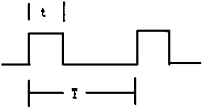
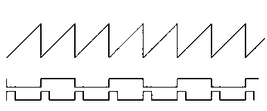
The invention discloses a vibration method used for a vibration handle. The vibration method includes the following steps that a control circuit board provides a power source for a coil electromagnet;the control circuit board processes received information and sends the processed information to a driver on the coil electromagnet; the driver on the coil electromagnet then sends an electric signalto directly control on and off of the coil electromagnet; and the coil electromagnet continuously controls the on and off processes, and therefore the back-and-forth movement of a magnetic bar is formed, and vibration of a vibration button is driven through the back-and-forth linear movement of the magnetic bar. The coil electromagnet serves as the vibration source and has the beneficial effects that the structure is simple, the size is small, work is reliable, and the frequency can be adjusted. The PWM signal range is adjustable, the movement frequency of the magnetic bar of the coil electromagnet can be maintained in the optimal state, meanwhile, low power consumption is achieved, and the heating problem caused by long-time work is avoided. Finally, the PWM frequency and the duty ratio are changed through a driving circuit, the movement speed and strength of the magnetic bar in the coil electromagnet are controlled, and therefore the vibration speed and the vibration strength of thevibration button are controlled.

Description

Technical field [0001] The invention relates to a vibration method for vibrating a handle, belonging to the field of electrical control. Background technique [0002] With the development and application of electrical control systems in non-road mobile machinery, control handles have gradually developed. At present, most of the handles used in the market are of basic general-purpose type, which can only meet general functional requirements, and have high safety requirements. It cannot meet the environmental requirements of some special use occasions. The traditionally adopted vibration method is the vibration method of an eccentric vibrator. The eccentric vibrator performs circular motion and has an intermediate transmission device. The vibrating handle using the eccentric vibrator consumes a lot of power, and it is easy to cause the handle to heat up under the condition of frequent vibration; secondly, the fixed vibration mode is easy to be interfered by the vibration of the ma...

Claims


Application Information

Patent Timeline
Patent Type & Authority Applications(China)
IPC IPC(8): B06B1/04H01F7/06
CPCB06B1/045H01F7/064
Inventor 王小路陈岭徐磊朱洁朱璧晖王文斌
Owner 江苏山河机电技术有限公司
Learn More