Valve body cleaning device

A cleaning device and valve body technology, applied in the direction of cleaning methods using liquids, cleaning methods and utensils, cleaning methods using tools, etc., can solve problems such as poor cleaning effect and inability to remove impurities on the surface of the valve body, so as to avoid Clean the dead angle, improve the matching effect, and ensure the effect of the limit effect

Active Publication Date: 2019-11-22
YUHUAN DAZHONG COPPER MFG CO LTD
View PDF7 Cites 3 Cited by
  • Summary
  • Abstract
  • Description
  • Claims
  • Application Information

AI Technical Summary

Problems solved by technology

[0003] The valve is generally composed of a valve body, a valve core, a handwheel and a threaded rod. The valve body needs to be inspected after it is manufactured. Magnetic particle inspection is one of the commonly used inspection methods. Before the magnetic particle inspection, the surface of the valve body needs to be cleaned. , in order to remove the grease on the surface of the valve body and avoid the influence of grease on the magnetic powder. When cleaning the valve body, it is inconvenient to clean the valve body due to the T-shaped structure of the valve body. The impact cleans the valve body, the cleaning effect is not good, and the impurities on the surface of the valve body cannot be effectively removed

Method used


Image

  • Valve body cleaning device
  • Valve body cleaning device
  • Valve body cleaning device

Examples


Embodiment Construction

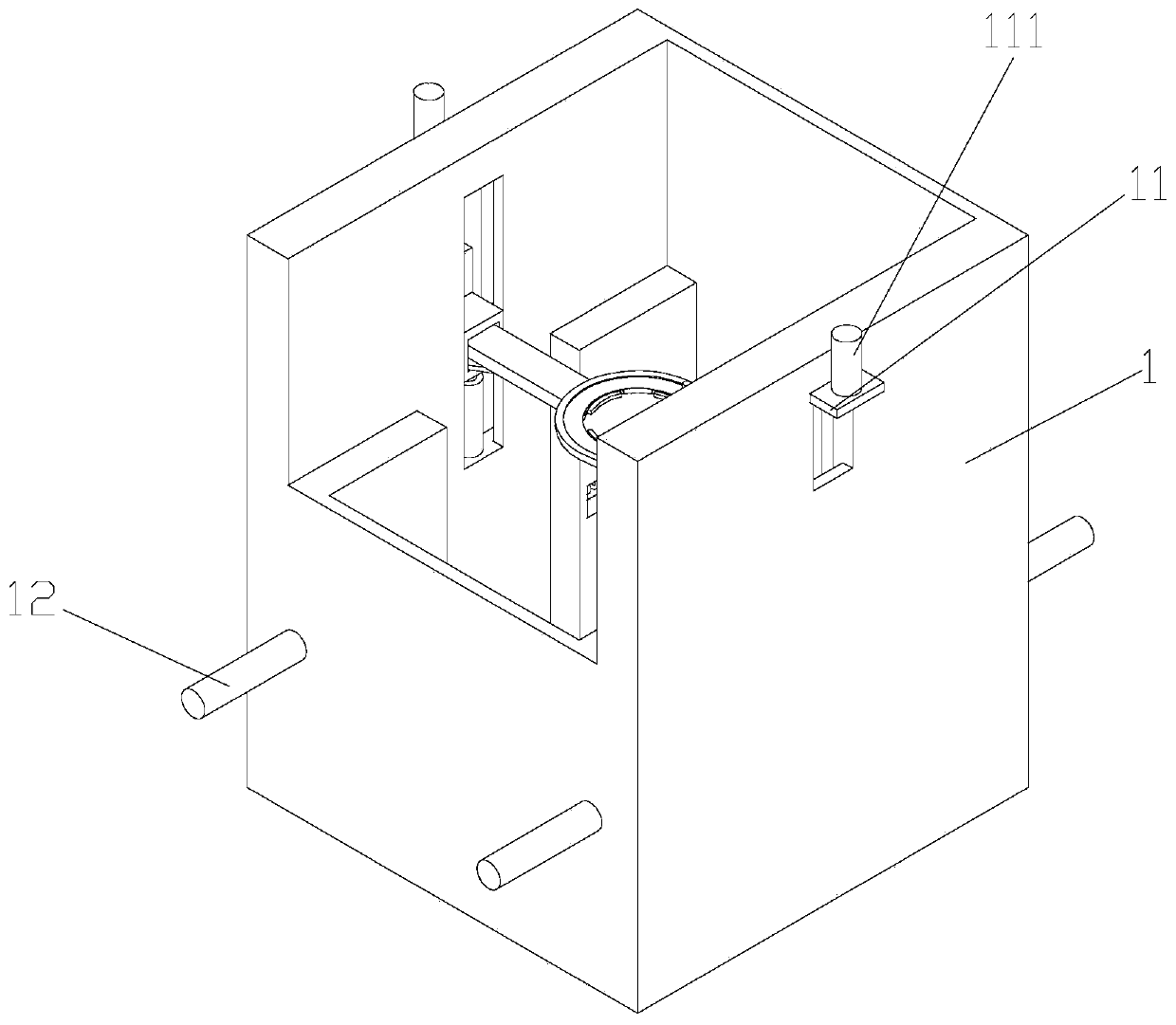
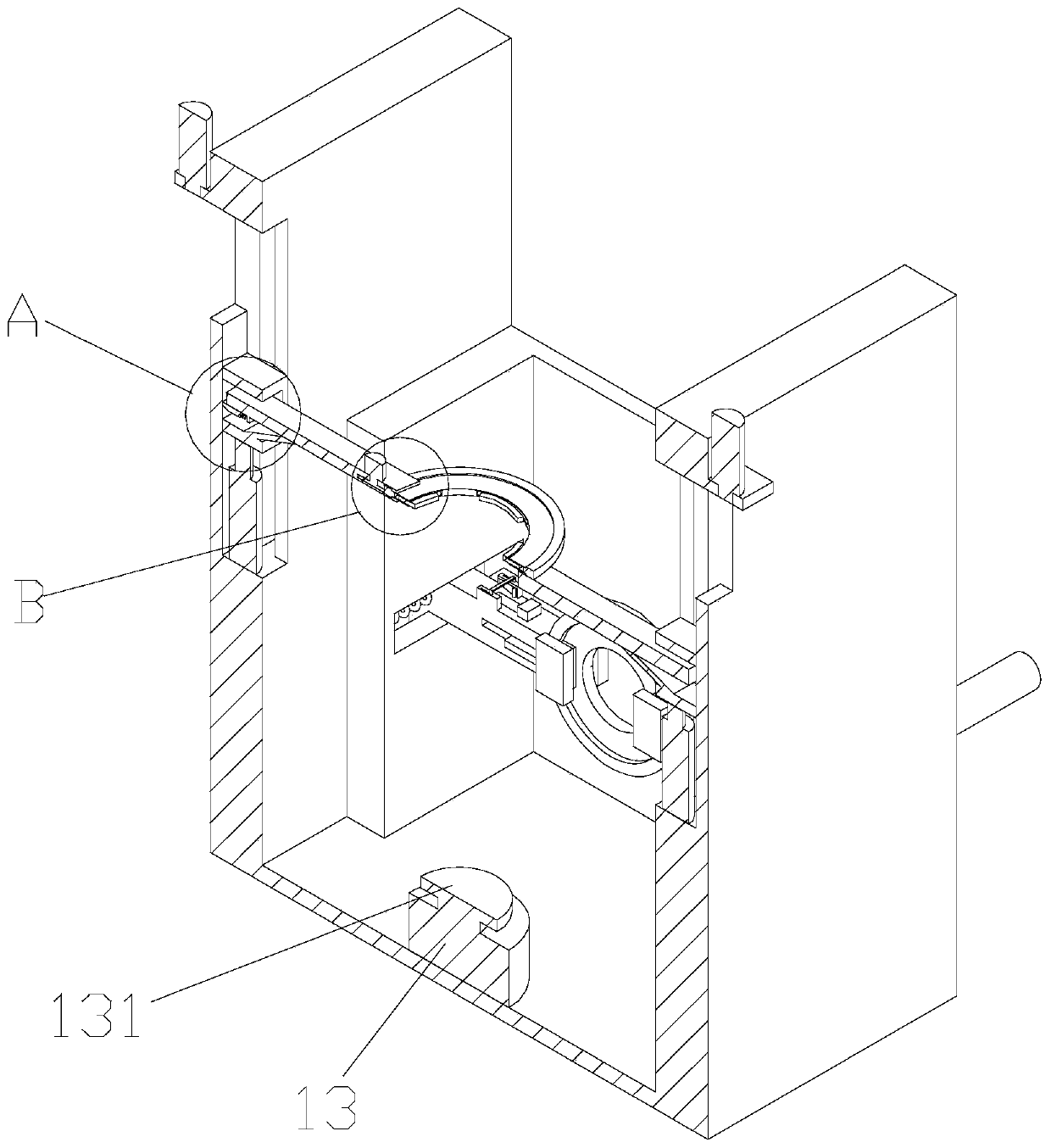
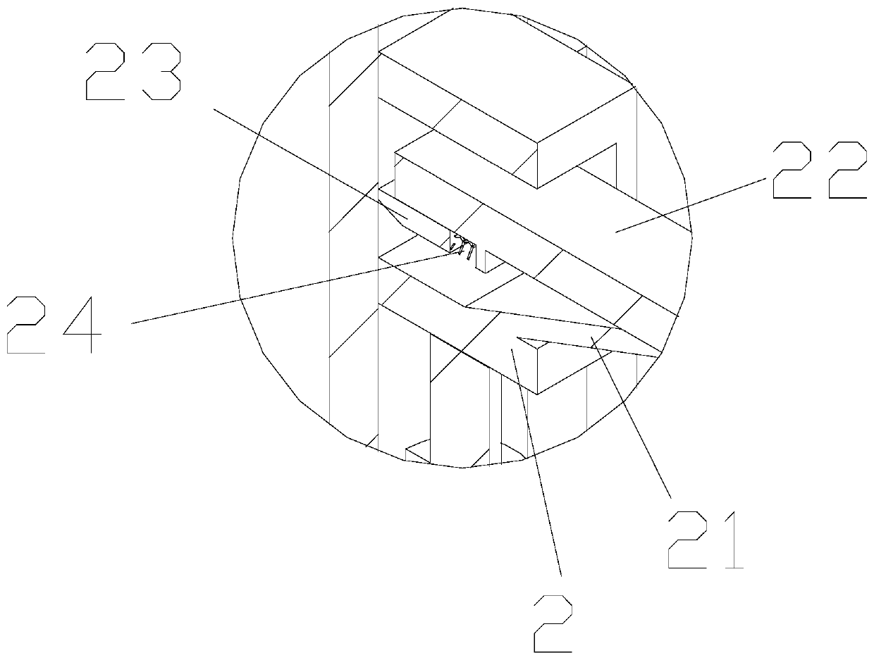
[0033] Such as Figure 1-17 As shown, a valve body cleaning device includes a cleaning box 1, a fixing assembly arranged in the cleaning box 1 and a cleaning assembly arranged in the cleaning box 1, and the inner wall of the cleaning box 1 is provided with Mounting block 14, described mounting block is four, is symmetrically arranged on the inner wall of described cleaning box, is provided with first movable groove on described mounting block 14, is provided with first movable block 3 in described first movable groove The side wall of the cleaning box 1 is provided with a first cylinder 12 matched with the first movable block 3, and the cleaning assembly includes a first connecting rod 33 arranged on the first movable block 3, which can Rotate the collar 32 that is located on the first connecting rod 33 and the first driving motor that is located on the first connecting rod 33, the first driving motor can drive the collar 32 to rotate, the collar A plurality of bristles are p...


PUM


Abstract

The invention discloses a valve body cleaning device. The device comprises a cleaning box, a fixed component arranged in the cleaning box, and a cleaning component arranged in the cleaning box, wherein a mounting block is arranged on the inner wall of the cleaning box; a first active groove is formed in the mounting block; a first active block is arranged in the first active groove; a first air cylinder matched with the first active block is arranged on the side wall of the cleaning box; the cleaning component comprises a first connecting rod arranged on the first active block, a lantern ringrotationally arranged on the first connecting rod, and a first driving motor arranged on the first connecting rod; the first driving motor can drive the lantern ring to rotate; a plurality of bristlesare arranged on the inner wall of the lantern ring; the fixed component can drive a valve body to rotate; after the valve body enters the cleaning box, the lantern ring moves to the position of the valve body, and the lantern ring ensures that the bristles are in sufficient contact with the surface of the valve body after sleeving the valve body, so that grease and impurities on the surface of the valve body are removed, and the cleaning efficiency of the valve body is enhanced.

Description

technical field [0001] The invention belongs to the technical field of valve manufacturing, in particular to a valve body cleaning device. Background technique [0002] Valves are pipeline accessories used to open and close pipelines, control flow direction, adjust and control the parameters (temperature, pressure and flow) of the conveying medium. According to its function, it can be divided into shut-off valve, check valve, regulating valve and so on. [0003] The valve is generally composed of a valve body, a valve core, a handwheel and a threaded rod. The valve body needs to be inspected after it is manufactured. Magnetic particle inspection is one of the commonly used inspection methods. Before the magnetic particle inspection, the surface of the valve body needs to be cleaned. , to remove the grease on the surface of the valve body and avoid the influence of grease on the magnetic powder. In the existing cleaning of the valve body, because the valve body is a T-shaped...

Claims


Application Information

Patent Timeline
Patent Type & Authority Applications(China)
IPC IPC(8): B08B1/00B08B1/04B08B3/08B08B3/10B08B13/00
CPCB08B1/008B08B1/002B08B1/04B08B3/08B08B3/10B08B13/00
Inventor 董服义
Owner YUHUAN DAZHONG COPPER MFG CO LTD
Why Eureka
Try Eureka