Batched bulk parts separating device, loading system and loading method

A technology for separating devices and parts, applied in the field of feeding systems, can solve the problems of limited specifications of bearing products, reduced production capacity, and inability to achieve, and achieves the effect of reducing design and debugging cycles, reducing production costs, and improving production efficiency

Pending Publication Date: 2019-11-22
无锡丹尼克尔自动化科技有限公司
View PDF0 Cites 3 Cited by
  • Summary
  • Abstract
  • Description
  • Claims
  • Application Information

AI Technical Summary

Problems solved by technology

The disadvantage is that the vibration plate is a non-standard product, which needs to be customized by the supplier according to the specifications of the parts to be carried. The specifications of the load-bearing products are limited. When replacing the product, it is often necessary to replace the equipment, redesign and debug, which takes a long time and has poor flexibility. It is difficult to debug and stabilize in a short time. When there are many types of parts, the coordination of the automatic assembly system is extremely cumbersome. Even debugging and replacement requires the presence of equipment suppliers, which delays production
In order to increase flexibility, the current practice is to equip manual assembly operators, but there are obvious defects in manual operation: 1) The repeatability and stability of loading materials are poor, due to human emotions, the influence of the environment, physical energy consumption and skill differences will lead to differences The loading status of the operator is unstable; 2) The loading accuracy is poor, because some products have precise requirements on the position and direction of the component loading, and manual loading cannot meet the requirements; 3) The loading efficiency is low, and the loading Time occupies a large proportion in the product processing link, and relying on manual feeding is very inefficient, thereby reducing production capacity; 4) Poor flexibility and adaptability. When the product type changes, a lot of training is required for operators and replacement of feeding materials equipment
The flexible feeding device is an attempt of the existing technology in the field of automatic assembly. The ideal state of feeding is that it can palletize or assemble multi-variety batch bulk parts of any geometric shape based on industrial vision systems and pick-and-place robots, which perfectly fits the current Automated feeding needs for multi-variety batch bulk parts, but the flexible feeding device is still in the initial stage of research and development, and the finished product model cannot reach the above ideal state

Method used


Image

  • Batched bulk parts separating device, loading system and loading method
  • Batched bulk parts separating device, loading system and loading method
  • Batched bulk parts separating device, loading system and loading method

Examples


Embodiment 1

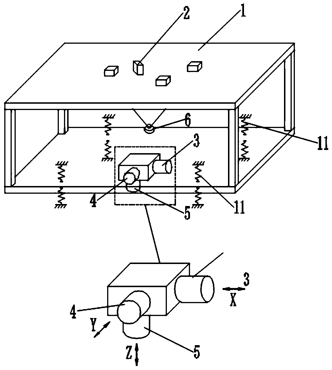
[0049] During specific implementation, the positional relationship between the X-axis force part, the Y-axis force part, the Z-axis force force part and the tray 1 is as follows: figure 1 shown.

[0050] The first electromagnet 3 is set in the X-axis force part, the second electromagnet 4 is set in the Y-axis force force part, the third electromagnet 5 is set in the Z-axis force force part, the first electromagnet 3, the second electromagnet 4, the third electromagnet The electromagnets 5 are all arranged at the bottom of the tray 1, the third electromagnet 5 is arranged at the bottom of the middle of the tray 1, the first electromagnet 3 is arranged beside the third electromagnet 5 and arranged along the X-axis direction, and the second electromagnet 4 is arranged at the bottom of the tray 1. Next to the third electromagnet 5 and arranged along the Y-axis direction, the first electromagnet 3 , the second electromagnet 4 and the third electromagnet 5 are electrically connected...

Embodiment 2

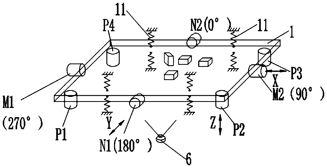
[0052] In this embodiment, the positional relationship between the X-axis force part, the Y-axis force part, the Z-axis force force part and the tray 1 is as follows image 3 shown.

[0053] The X-axis force part is set in the X-axis direction, the Y-axis force force part is set in the Y-axis direction, and the Z-axis force force part is set in the Z-axis direction. The coordinate origin of the X-axis, Y-axis and Z-axis is at the center of gravity of the tray 1 On the vertical axis, the X-axis force part, the Y-axis force force part, and the Z-axis force force part are distributed along the vertical axis of the center of the tray. The X-axis force force part, the Y-axis force force part, and the Z-axis force force part The direction of action of the action points to the tray 1, and the X-axis force part, the Y-axis force force part and the Z-axis force force part are electrically connected with the control part.

[0054] In order to realize the force on the tray 1, the X-axis...


PUM


Abstract

The invention discloses a batched bulk parts separating device, a loading system and a loading method. The device comprises a base, a supporting part and a tray. The supporting part is connected to the base, the tray is arranged on the supporting part, a tray stressing part is arranged on the base, the tray stressing part is connected to a control part, the action direction of the tray stressing part is one or more of X axis, Y axis and Z axis, and the tray responses to action of the tray stressing part; and the loading system comprises the separating device, a stock bin, a CCD photographic system, a manipulator, a material platform and a control system. The separating device has the advantages that the separating device separates batched bulk parts and makes the parts in expected gestureswithin a given time; by defining the direction, the parts can be conveyed to any areas; matched with the loading system, the parts are loaded automatically and flexibly; the same device can be suitable for parts of different specifications; when products are replaced, control parameters are only regulated according to the parts, so that the production efficiency is improved and the production cost is lowered.

Description

technical field [0001] The invention belongs to the field of automatic assembly equipment, and in particular relates to a separation device for separating batches of bulk parts and making them in a desired posture within a given time, a feeding system and a feeding method with the separation device. Background technique [0002] Assembly refers to the combination of several parts of the product through tight fit, buckle, screw connection, bonding, riveting, welding, etc. to obtain a finished or semi-finished product that meets the predetermined dimensional accuracy and function. The assembly realized by manual processing (touching, sorting, grabbing, moving, placing, applying force, etc.) of each component is called manual assembly. Assembly that does not require manual handling (touching, sorting, grabbing, moving, placing, applying force, etc.) of components is called automatic assembly. In between is semi-automatic assembly. In the prior art, most parts are supplied in ...

Claims


Application Information

Patent Timeline
Patent Type & Authority Applications(China)
IPC IPC(8): B23P19/00
CPCB23P19/004B23P19/007
Inventor 汪洋
Owner 无锡丹尼克尔自动化科技有限公司
Why Eureka
Try Eureka