Conveying and cutting device for production of polystyrene foam boards
A technology of polystyrene foam and cutting equipment, which is applied in the direction of metal processing, etc., can solve the problems of increasing manual labor intensity, low efficiency of adjustment process, and inability to complete cutting, so as to save manual distance adjustment process, high cutting efficiency, Labor saving effect
- Summary
- Abstract
- Description
- Claims
- Application Information
AI Technical Summary
Problems solved by technology
Method used
Image

Examples
Embodiment Construction
[0029] In order to further understand the content of the invention, features and effects of the present invention, the following examples are given in detail as follows:
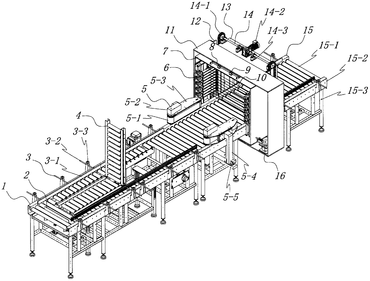
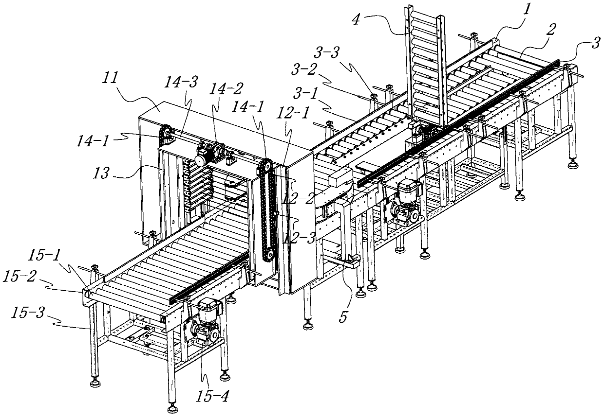
[0030] See figure 1 with figure 2 , the conveying and cutting equipment for polystyrene foam board production of the present invention comprises a material turning transport device 1 with a gap on the transmission surface, and a material turning device capable of turning materials at 0 / 90 degrees is provided in the gap of the material turning transport device 1 Device 4; Upstream of the material turning device 4, a material blocking device 2 connected to the material turning transport device 1 for blocking / releasing materials from entering the material turning device 4 is provided.
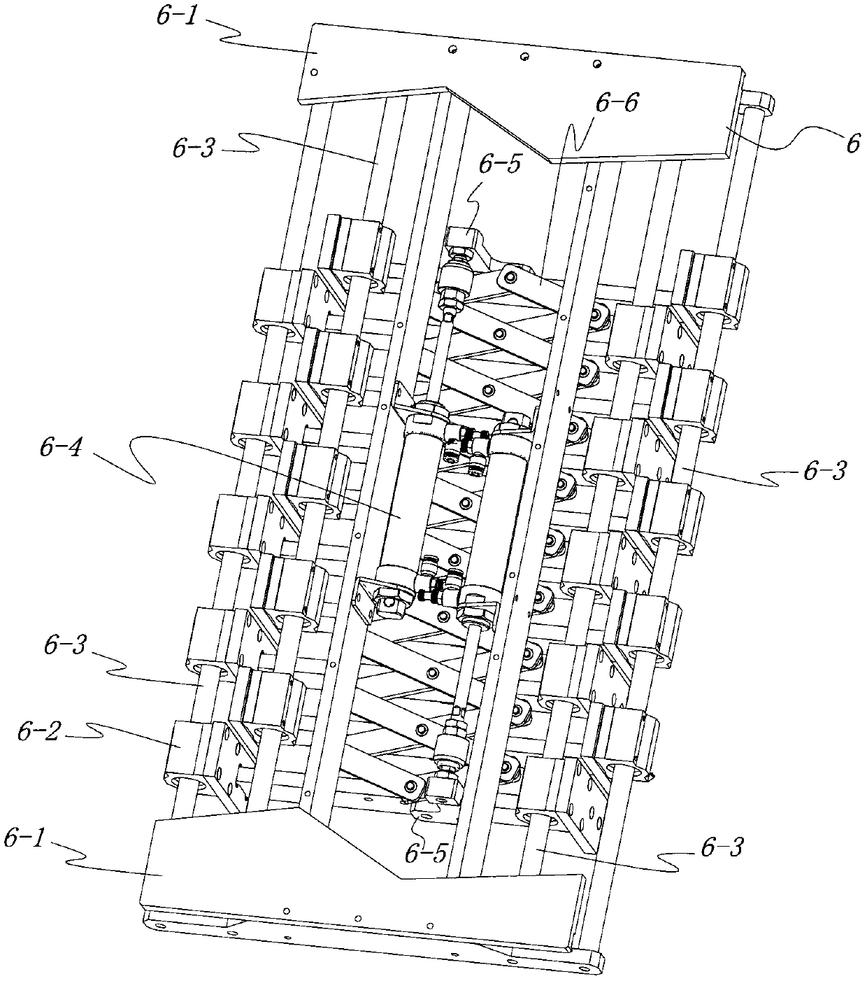
[0031] see further Image 6 , the material turning transport device 1 comprises a material turning transport support 1-1, two sets of material turning transport side plates 1-3 are fixedly connected to the top of the material...
PUM
 Abstract
Description
Claims
Application Information