Turnover mechanism of engraving and milling machine

A technology of turning mechanism and engraving and milling machine, which is applied in the direction of multi-purpose machinery, forming/shaping machine, special forming/shaping machine, etc. It can solve problems such as difficult to realize efficient automatic processing, and achieve the effect of simplifying moving components

Pending Publication Date: 2019-11-22
吴善旺
View PDF13 Cites 2 Cited by
  • Summary
  • Abstract
  • Description
  • Claims
  • Application Information

AI Technical Summary

Problems solved by technology

[0005] The purpose of the present invention is to solve the above-mentioned problems in the existing technology, and propose a turning mechanism of an engraving and milling machine to solve the problem that the existing engraving and milling machine is difficult to realize efficient automatic processing for different sides of wood

Method used


Image

  • Turnover mechanism of engraving and milling machine
  • Turnover mechanism of engraving and milling machine
  • Turnover mechanism of engraving and milling machine

Examples


Embodiment 1

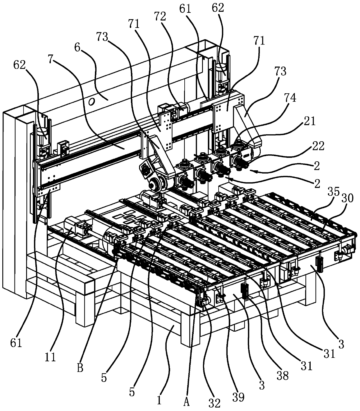
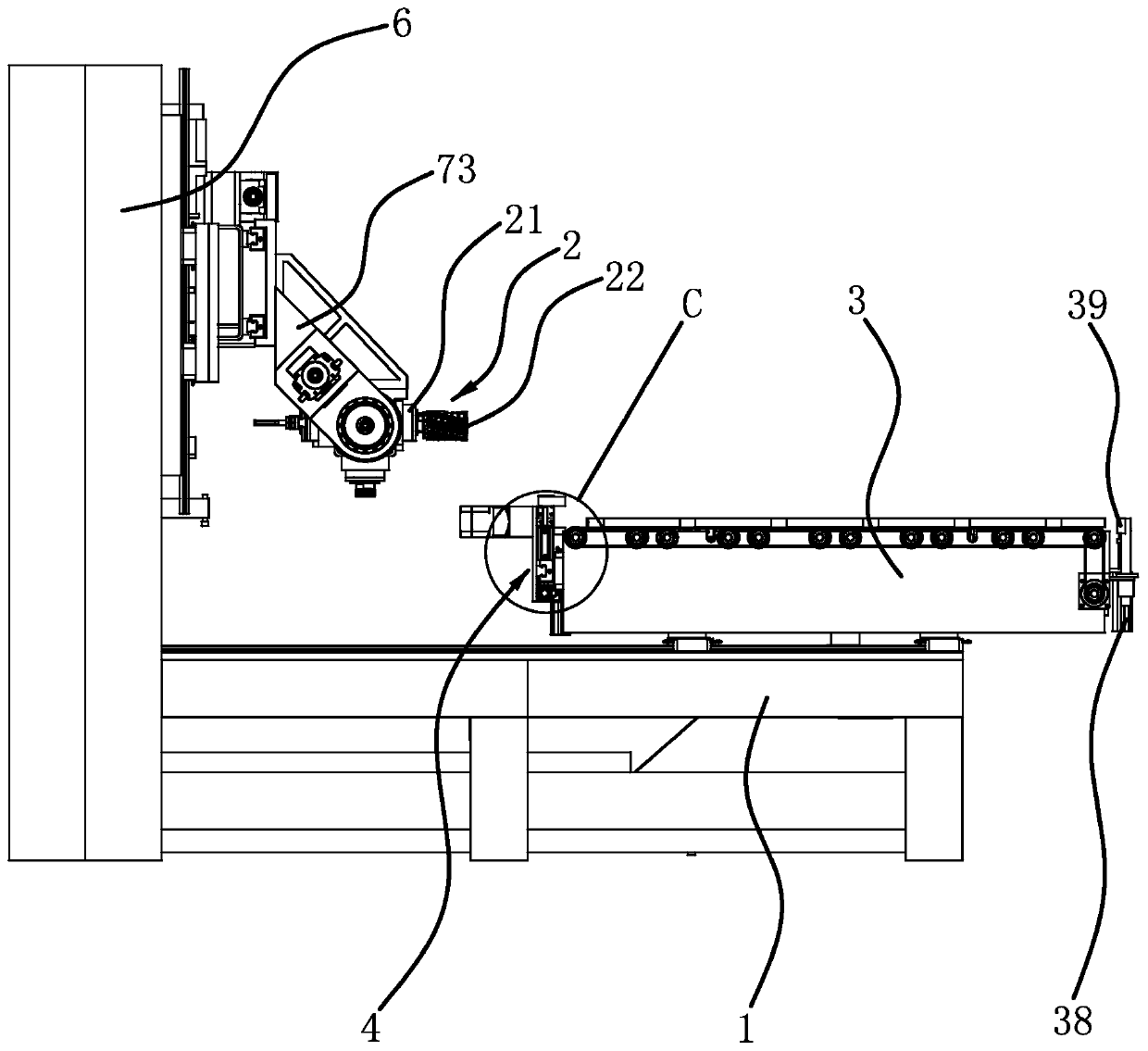
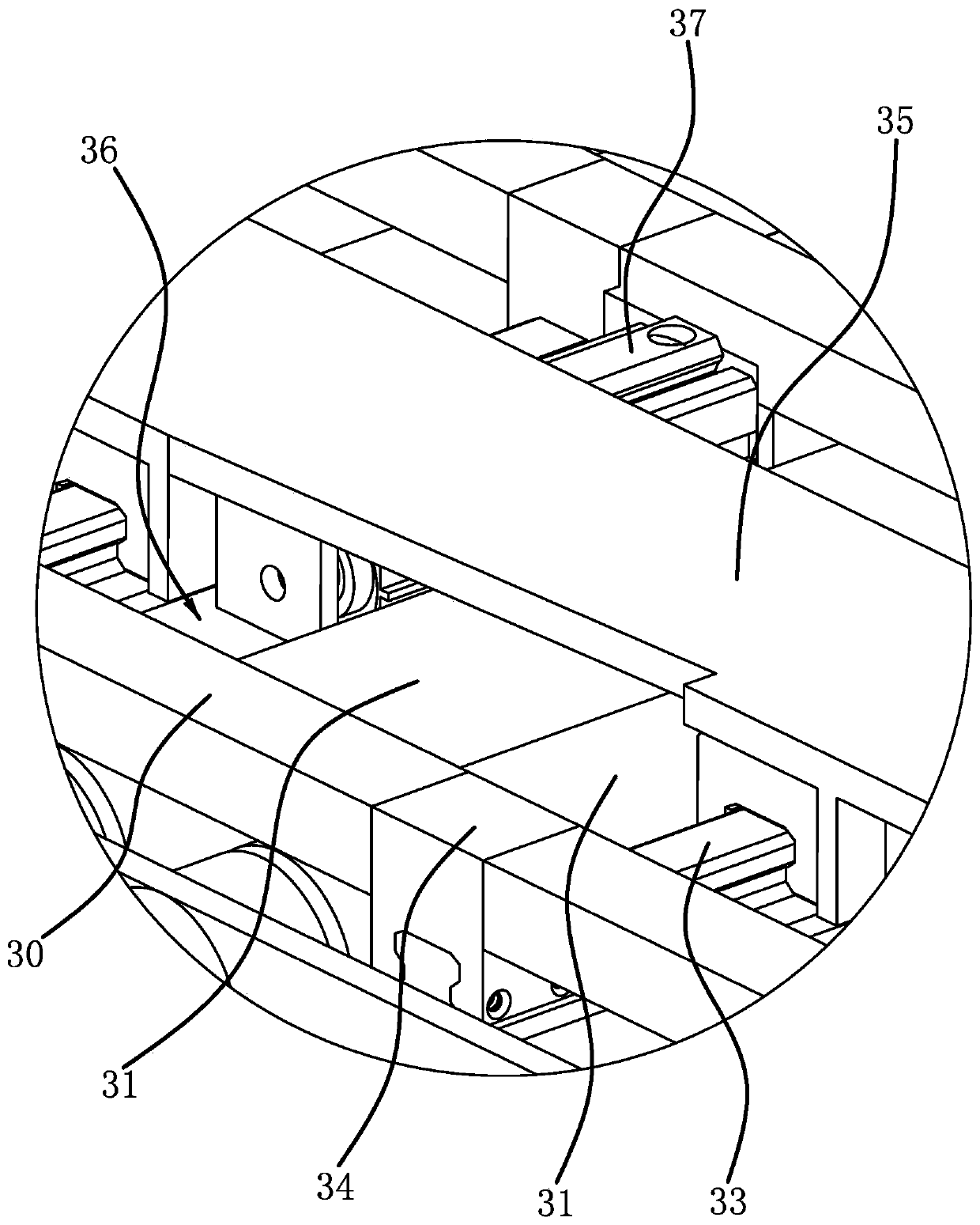
[0032] Such as figure 1 , figure 2 As shown, the turning mechanism of the engraving and milling machine, the engraving and milling machine includes a frame 1, a processing component 2 and a processing platform 3, a gantry 6 is fixed on the frame 1, and the two columns of the gantry 6 are vertically slid and connected with vertical The carriage 61 is fixed with a crossbeam 7 arranged horizontally between the two vertical carriages 61. The crossbeam 7 is driven vertically through the cooperation of the vertical motor 62 and the screw nut assembly. Plate 71, the horizontal drag plate 71 is driven horizontally through the cooperation of the horizontal motor 72 and the screw nut assembly. The horizontal drag plate 71 has two pieces, and each horizontal drag plate 71 is fixed with a support seat 73, between the two support seats 73 There is a strip-shaped tool holder 74 that is rotatably connected to each other, and the tool holder 74 is arranged laterally. There are multiple proc...

Embodiment 2

[0037] The turning mechanism of the engraving and milling machine is basically the same as the structure of the first embodiment, the difference is that Figure 7 As shown, the gantry 6 is slidingly connected to the frame 1 in the longitudinal direction, and the longitudinal motor 11 cooperates with the screw nut assembly to drive the gantry 6 to move in the longitudinal direction. Correspondingly, the processing platform 3 only needs to be fixed on the frame 1 That is, at this time, the moving assembly 4 can be set on the processing platform 3 or directly on the frame 1 .

Embodiment 3

[0039] The turning mechanism of the engraving and milling machine is basically the same as the structure of the first embodiment, the difference is that Figure 8 As shown, clamps 5 all include rotary cylinders 57, and several rotary cylinders 57 are fixed on the moving plate 41 and arranged horizontally.


PUM


Abstract

The invention provides a turnover mechanism of an engraving and milling machine, belongs to the technical field of machining equipment, and solves the problem that an existing engraving and milling machine is hard to automatically machine different side faces of a wood material efficiently. According to the turnover mechanism of the engraving and milling machine, the engraving and milling machinecomprises a rack and a machining assembly arranged on the rack. A machining platform capable of conveying the wood material longitudinally is also arranged on the rack, the machining assembly can translate three-dimensionally relative to the machining platform, the overturn mechanism comprises a clamp capable of clamping the wood material and driving the wood material to overturn, a moving assembly is arranged on the machining platform, the clamp is arranged on the moving assembly, the moving assembly can drive the clamp to move along a vertical direction, and the clamp is located at one longitudinal end of the machining platform. The turnover mechanism of the engraving and milling machine can machine different side faces of the wood material automatically.

Description

technical field [0001] The invention belongs to the technical field of mechanical processing equipment, and relates to a turning mechanism of an engraving and milling machine. Background technique [0002] Engraving and milling machine is a kind of CNC machine tool, which can be used for both engraving and milling. It is a high-efficiency and high-precision CNC machine tool with a wide range of applications. For example, the engraving and milling machine disclosed in the patent document (201510945613.7) includes machine base, Horizontal moving table, support plate, moving device and engraving and milling mechanism, horizontal moving table is connected to machine base through driving mechanism, positioning supporting mechanism is arranged on the top surface of horizontal moving table, moving device includes positioning frame and moving mechanism, positioning frame A first motor is arranged on one side, and a limit block is arranged on the other side of the positioning frame. ...

Claims


Application Information

Patent Timeline
Patent Type & Authority Applications(China)
IPC IPC(8): B27C5/02B27C5/06B27C9/04
CPCB27C5/02B27C5/06B27C9/04
Inventor 吴善旺
Owner 吴善旺
Why Eureka
Try Eureka