
Efficient aerator based on shallow aeration principle

An aerator and aeration technology, applied in water aeration, sustainable biological treatment, chemical instruments and methods, etc., can solve the problems of high energy consumption, membrane aging, affecting stability, etc., and achieve high oxygen utilization efficiency , The effect of strong oxygenation capacity and small airflow resistance

Pending Publication Date: 2019-11-22
山东问清智能装备有限公司
View PDF0 Cites 3 Cited by
  • Summary
  • Abstract
  • Description
  • Claims
  • Application Information

AI Technical Summary

Problems solved by technology

At present, the aeration device powered by air source generally adopts diaphragm microporous aerator or inverted umbrella aerator. Diaphragm microporous aerator has problems such as diaphragm aging, rupture and blockage during use. , resulting in higher maintenance and replacement costs, affecting the stability of use
In addition, when the depth of the water is large during operation, the rising medium and small air bubbles tend to converge into large air bubbles, which reduces the oxygen conversion efficiency.
The inverted umbrella type aerator has a relatively low immersion degree and is not suitable for deep aeration tanks. It needs to drive the impeller to rotate through a motor through a multi-stage reducer, which has high energy consumption and low efficiency.

Method used


Image

  • Efficient aerator based on shallow aeration principle
  • Efficient aerator based on shallow aeration principle
  • Efficient aerator based on shallow aeration principle

Examples


Embodiment Construction

[0028] The following will clearly and completely describe the technical solutions in the embodiments of the present invention with reference to the accompanying drawings in the embodiments of the present invention. Obviously, the described embodiments are only some, not all, embodiments of the present invention. Based on the embodiments of the present invention, all other embodiments obtained by persons of ordinary skill in the art without making creative efforts belong to the protection scope of the present invention.

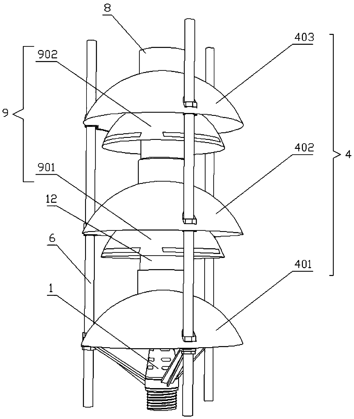
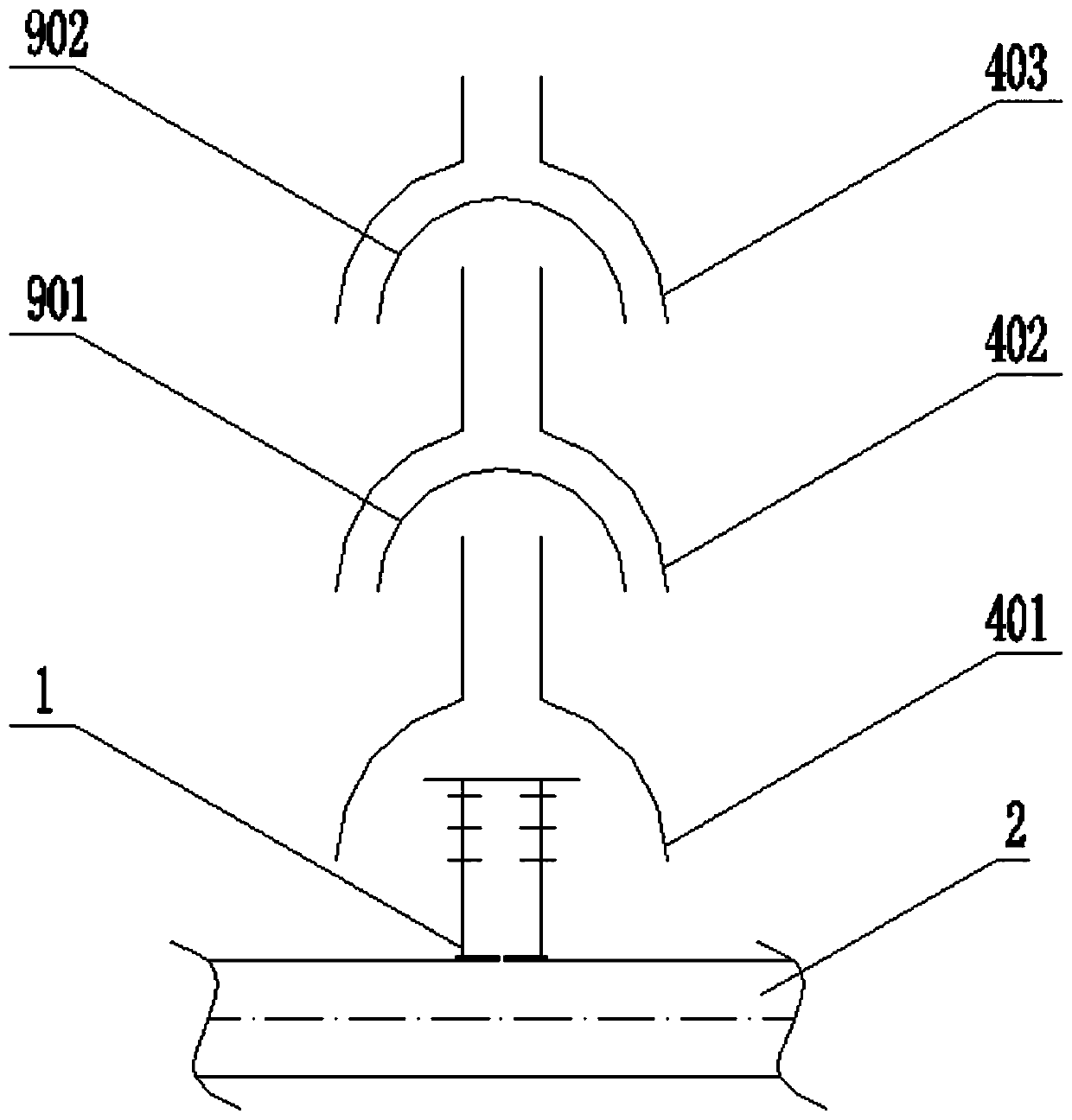
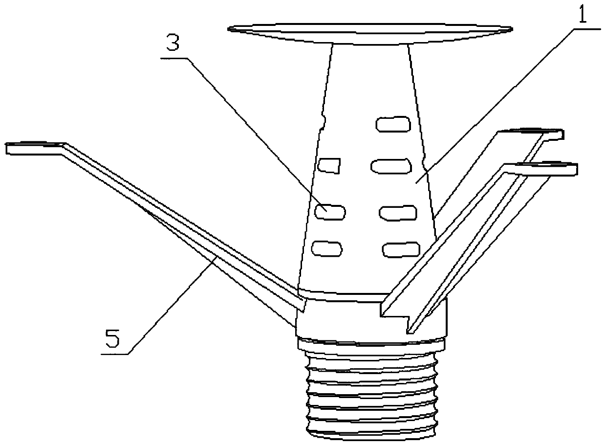
[0029] Such as figure 1 with figure 2 as shown,

[0030] A high-efficiency aerator based on the principle of shallow aeration, including a slit air distribution pipe, a diversion umbrella cover and an overflow umbrella cover,

[0031] The bottom end of the slit-type air distribution pipe 1 communicates with the air supply pipe 2. The bottom of the slit-type air distribution pipe 1 can be welded to the air supply pipe 2 or can be connected to the air supply ...


PUM


Abstract

The invention discloses an efficient aerator based on a shallow aeration principle, which comprises a slit-type gas distribution pipe, wherein the bottom end of the slit-type gas distribution pipe iscommunicated with a gas supply pipe, the top end of the slit-type gas distribution pipe is closed, and a plurality of gas distribution slits are uniformly distributed on the side wall of the slit-typegas distribution pipe; the flow guide umbrella-shaped cover comprises a flow guide cover body and a flow guide pipe; the flow guide pipe is communicated with the top of the flow guide cover body; theslit type air distribution pipe is located on the inner side of the bottommost flow guide umbrella-shaped cover; the overflow umbrella-shaped cover comprises at least two layers of overflow umbrella-shaped cover bodies, each overflow umbrella-shaped cover body comprises an overflow cover body; besides the flow guide cover body located on the bottommost layer, the overflow cover bodies are arranged below the other flow guide cover bodies respectively. According to the shallow aeration principle, the design is unique, small bubbles are generated through collision of air in the flow guide umbrella-shaped cover and the overflow umbrella-shaped cover, and the air-water interface is increased; through multiple collisions, small bubbles are forced to be generated and broken for multiple times, and a gas-water interface is rapidly updated, so that the oxygen utilization efficiency is high, and the oxygenation capacity is high.

Description

technical field [0001] The invention relates to the technical field of water treatment, in particular to a high-efficiency aerator based on the principle of shallow aeration. Background technique [0002] The aerator is an important device used to increase the oxygen content of the sewage in the water treatment process. A large amount of air or oxygen is sent into the sewage through the aerator to make it generate bubbles to exchange oxygen with the sewage. At present, the aeration device powered by air source generally adopts diaphragm microporous aerator or inverted umbrella aerator. Diaphragm microporous aerator has problems such as diaphragm aging, rupture and blockage during use. , resulting in higher maintenance and replacement costs, affecting the stability of use. In addition, when the depth of water is large during operation, the rising medium and small air bubbles tend to converge into large air bubbles, which reduces the oxygen conversion efficiency. The inverte...

Claims


Application Information

Patent Timeline
IPC IPC(8): C02F7/00
CPCC02F7/00Y02W10/10
Inventor 王曙光段成彩
Owner 山东问清智能装备有限公司
Learn More