Liquid metal pouring melt sampling and analyzing device
A sampling analysis and liquid metal technology, applied in the field of metal processing, can solve the problems of high temperature burns on the operator's hand and high heat of the sampling cylinder, and achieve the effect of improving the ease of operation and improving the sealing performance.
- Summary
- Abstract
- Description
- Claims
- Application Information
AI Technical Summary
Problems solved by technology
Method used
Image
Examples
Embodiment 1
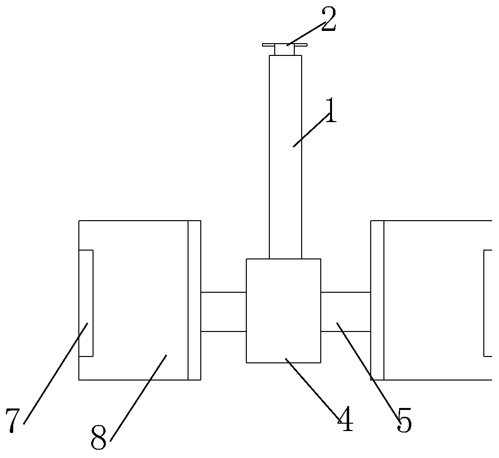
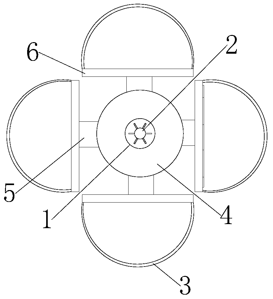
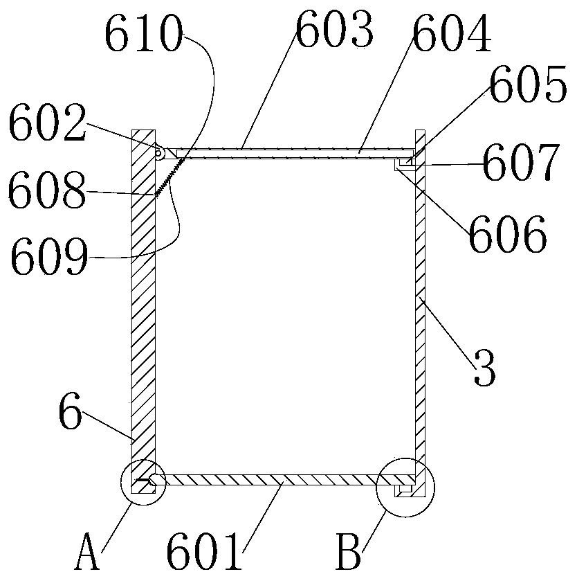
[0038] see Figure 1-6, is a schematic diagram of the overall structure of a liquid metal pouring melt sampling and analysis device, including a central cylinder 4, the central cylinder 4 is set in a cylindrical shape, the top of the central cylinder 4 is provided with an upright lifting rod 1, and the top axis of the lifting rod 1 is Pulling rods 2 are installed at the position, and hanging rods 5 are installed at equal intervals on the outer surface of the central cylinder 4. The hanging rods 5 are perpendicular to the carrying rod 1. The top of each hanging rod 5 is fixed with a sampling cylinder 8, and the outer wall of the sampling cylinder 8 Observation window 7 is arranged, and the middle of observation window 7 is provided with high-temperature-resistant transparent glass, and the material that this high-temperature-resistant glass uses is No. 4 material glass, and the glass of No. 4 material is below 1200 degrees.
[0039] The sampling cylinder 8 includes a straight p...
Embodiment 2
[0052] see Figure 1-7 , is a schematic diagram of the overall structure of a liquid metal casting melt sampling and analysis device. This embodiment has the same content as the above-mentioned embodiment 1, and the same will not be described in this embodiment. The specific differences are:
[0053] A circular hole 401 is arranged inside the central cylinder 4, and a hollow structure support column 402 is provided at the axial center of the bottom end of the circular hole 401. The top of the support column 402 is provided with a snap-in groove, and the top of the support column is provided with equidistantly distributed The clamping groove is set as a U-shaped groove with the opening facing upwards. The outer wall of the central cylinder 4 is provided with square holes 404 at equal intervals. The square holes 404 and the circular holes 401 are connected. There are two symmetrically distributed sliding holes 403, wherein the top of each square hole 404 has the same height, and...
PUM
 Abstract
Description
Claims
Application Information
 - R&D
- Intellectual Property
- Life Sciences
- Materials
- Tech Scout
- Unparalleled Data Quality
- Higher Quality Content
- 60% Fewer Hallucinations
Browse by: Latest US Patents, China's latest patents, Technical Efficacy Thesaurus, Application Domain, Technology Topic, Popular Technical Reports.
© 2025 PatSnap. All rights reserved.Legal|Privacy policy|Modern Slavery Act Transparency Statement|Sitemap|About US| Contact US: help@patsnap.com


