Rotating speed detecting method and device for bulb rotor of rotary anode

A technology of rotor speed and rotating anode, which is applied to devices using electric/magnetic methods, measuring devices, linear/angular velocity measurement, etc.

Active Publication Date: 2019-11-22
博玮科技(北京)有限公司
View PDF8 Cites 2 Cited by
  • Summary
  • Abstract
  • Description
  • Claims
  • Application Information

AI Technical Summary

Problems solved by technology

However, it is difficult to detect the rotor speed of the rotating anode X-ray tube. The conventional mechanical synchronous vibration detection method cannot detect the rotor speed in real time and there is a problem of reading error.

Method used


Image

  • Rotating speed detecting method and device for bulb rotor of rotary anode
  • Rotating speed detecting method and device for bulb rotor of rotary anode
  • Rotating speed detecting method and device for bulb rotor of rotary anode

Examples


Embodiment Construction

[0035] The following will clearly and completely describe the technical solutions in the embodiments of the present invention with reference to the accompanying drawings in the embodiments of the present invention. Obviously, the described embodiments are only some, not all, embodiments of the present invention. Based on the embodiments of the present invention, all other embodiments obtained by persons of ordinary skill in the art without making creative efforts belong to the protection scope of the present invention.

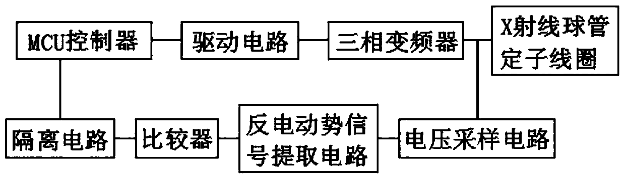
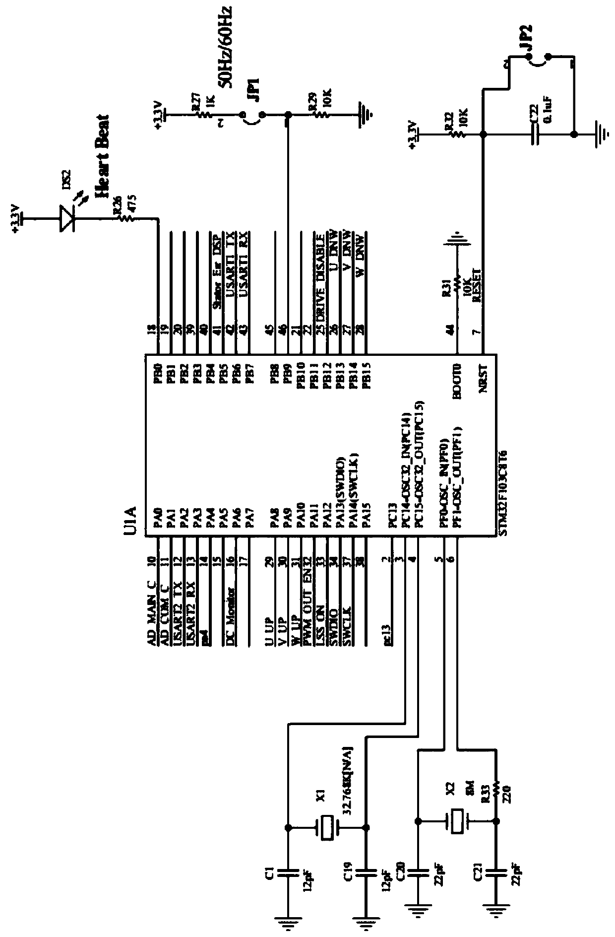
[0036] see Figure 1-7 , an embodiment provided by the present invention: a method for detecting the rotational speed of a rotating anode tube rotor, comprising the following steps:

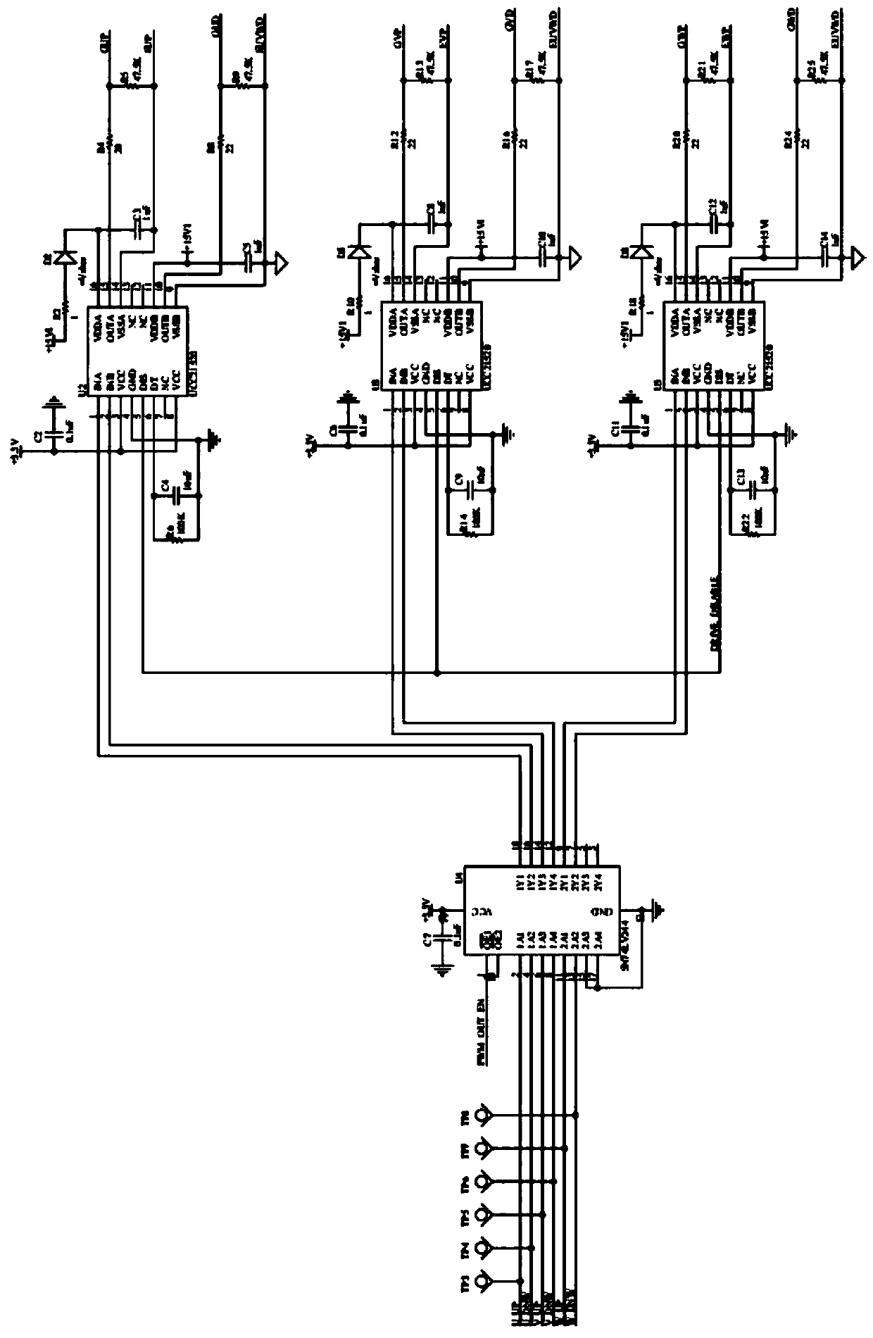
[0037] S1: The MCU controller generates SPWM control sequences intermittently through the control algorithm to drive the three-phase inverter to generate corresponding AC output;

[0038] S2: The three AC output terminals of the three-phase inverter are connected to the stator c...


PUM


Abstract

The invention discloses a rotating speed detecting method and device for a bulb rotor of a rotary anode. The method comprises the following steps that S1, an MCU controller intermittently generates anSPWM control sequence through a control algorithm so as to drive a three-phase frequency converter to generate corresponding AC output; S2, three alternating-current output ends of the three-phase frequency converter are connected to an X-ray bulb stator coil so as to drive the X-ray bulb rotor to rotate; and S3, induction voltage is mutually induced from two of the three AC output ends of the three-phase frequency converter so as to acquire a reverse electromotive force voltage with the same frequency as the X-ray bulb rotor. According to the invention, a voltage sampling circuit is embedded into the three-phase frequency converter, rotating speed information of the rotor is obtained through reverse electromotive force in an intervention mode and is read accurately and monitored in realtime, and the problems that the rotating speed of the X-ray bulb rotor is difficult to detect and cannot be detected in real time through a conventional mechanical synchronous vibration detection means, and that reading errors exist are solved.

Description

technical field [0001] The invention relates to the technical field of detecting the rotational speed of an anode bulb tube rotor, in particular to a method and a device for detecting the rotational speed of a rotating anode bulb tube rotor. Background technique [0002] The rotating anode tube is a high-performance tube after the emergence of high-power X-ray machines. This tube can work with a larger current in a small focus. X-ray generators are used in various applications of X-ray It is widely used in devices, for example, devices that use X-rays to expose images, and have a very large impact in the field of medical imaging. At present, the rotating speed of the rotating anode tube rotor is above 3000 rpm, the high-speed rotating anode tube can reach 7200 rpm, and the ultra-high-speed tube can reach above 10,000 rpm. The tube anode rotor speed is It is designed according to the focus current density of the tube. For the same current tube, the smaller the focus, the hig...

Claims


Application Information

Patent Timeline
Patent Type & Authority Applications(China)
IPC IPC(8): G01P3/48G05B19/042H01J35/10
CPCG01P3/4805H01J35/101G05B19/042
Inventor 胡文辉
Owner 博玮科技(北京)有限公司
Why Eureka
Try Eureka