Visual hole finding method and device, equipment and storage medium

A visual and hole alignment technology, applied in the field of visual recognition, can solve the problem that the insert cannot be accurately inserted into the socket of the pallet, and achieve the effect of accurately holding up the goods

Active Publication Date: 2019-11-22
国以贤智能科技(上海)股份有限公司
View PDF5 Cites 0 Cited by
  • Summary
  • Abstract
  • Description
  • Claims
  • Application Information

AI Technical Summary

Problems solved by technology

[0004] The hole-finding method in the prior art has the problem that the cutting strip

Method used


Image

  • Visual hole finding method and device, equipment and storage medium
  • Visual hole finding method and device, equipment and storage medium
  • Visual hole finding method and device, equipment and storage medium

Examples


Embodiment 1

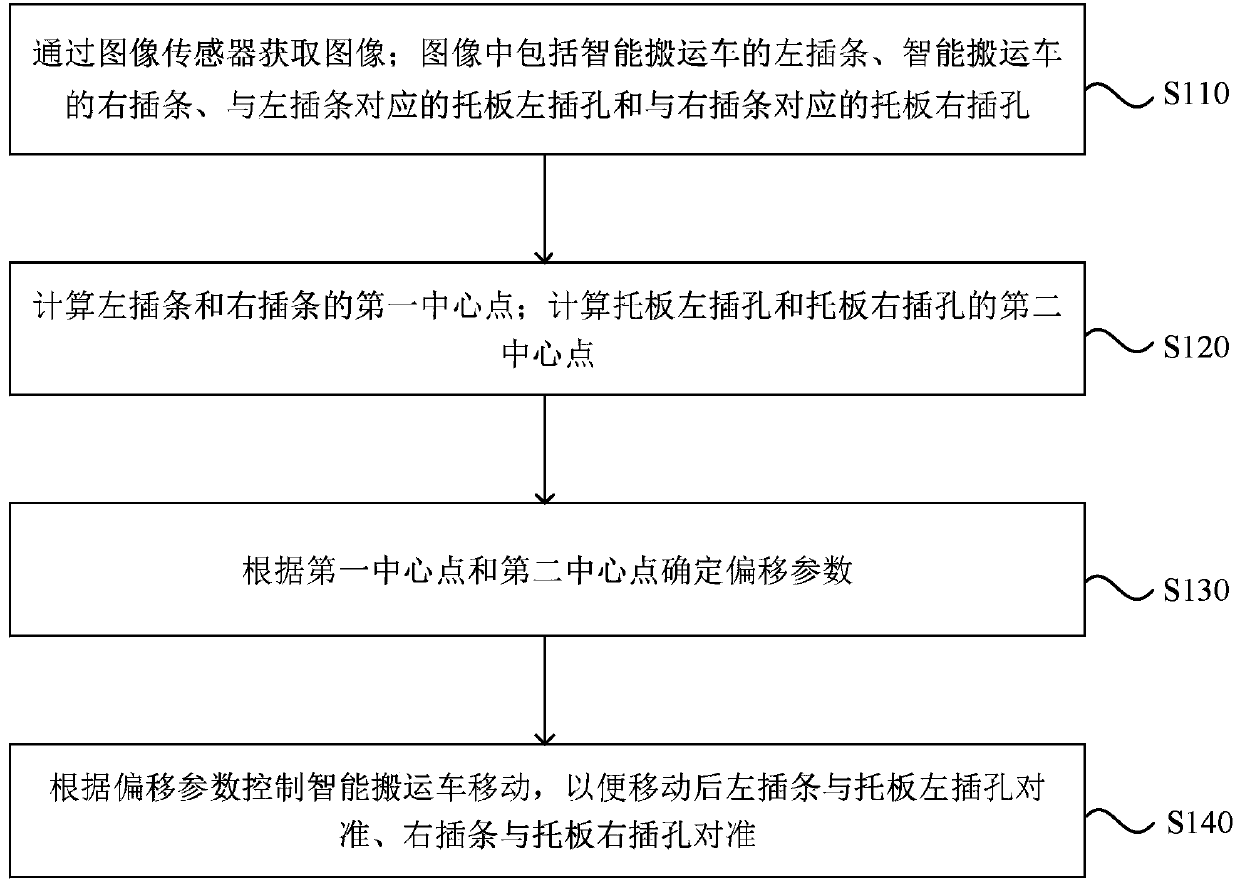
[0027] figure 1 It is a flow chart of a visual hole-finding method in Embodiment 1 of the present invention. This embodiment can be applied to intelligent trucks. This method can be performed by a visual hole-finding device, which can be implemented by means of software and / or hardware Realize, and integrate into the device that executes the method. In this embodiment, the device that executes the method may be any smart terminal such as a computer, a tablet computer, and / or a mobile phone. Specifically, refer to figure 1 , the method specifically includes the following steps:

[0028] S110. Acquiring an image through the image sensor; the image includes the left insert of the smart truck, the right insert of the smart truck, the left socket of the pallet corresponding to the left socket, and the right socket of the pallet corresponding to the right socket .

[0029] Specifically, an image is captured by an image sensor installed on an intelligent transport vehicle, wherein...

Embodiment 2

[0043] Figure 4 It is a schematic structural diagram of a visual hole-finding device in Embodiment 2 of the present invention. The device can be applied to intelligent trucks, and the device can be realized by software and / or hardware. like Figure 4 As shown, the device includes: an image acquisition module 410 , a center point calculation module 420 , an offset parameter determination module 430 and an intelligent transport vehicle movement module 440 .

[0044] Wherein, the image acquisition module 410: used to acquire an image through an image sensor; the image includes the left insert of the intelligent transport vehicle, the right insert of the intelligent transport vehicle, the left jack of the pallet corresponding to the left insert and the right insert The corresponding socket on the right side of the pallet;

[0045] Center point calculation module 420: used to calculate the first center point of the left insert and the right insert; calculate the second center po...

Embodiment 3

[0059] Figure 5 A schematic structural diagram of a device provided in Embodiment 3 of the present invention, such as Figure 5 As shown, the device includes a processor 50, a memory 51, an input device 52 and an output device 53; the number of processors 50 in the device can be one or more, Figure 5 Take a processor 50 as an example; the processor 50, memory 51, input device 52 and output device 53 in the device can be connected by bus or other methods, Figure 5 Take connection via bus as an example.

[0060] Memory 51, as a computer-readable storage medium, can be used to store software programs, computer-executable programs and modules, such as program instructions / modules corresponding to the visual hole-finding method in the embodiment of the present invention (for example, image acquisition module 410, center point calculation module 420, offset parameter determination module 430 and intelligent transport vehicle movement module 440). The processor 50 executes vari...


PUM


Abstract

An embodiment of the invention discloses a visual hole finding method and device, equipment and a storage medium which can be applied to an intelligent truck. The visual hole finding method comprisesa step of acquiring an image through an image sensor, wherein the image includes a left insertion strip of the intelligent truck, a right insertion strip of the intelligent truck, a pallet left insertion hole corresponding to the left insertion strip, and a pallet right insertion hole corresponding to the right insertion strip, a step of calculating first center points of the left insertion stripand the right insertion strip, a step of calculating second center points of the pallet left insertion hole and the pallet right insertion hole, a step of determining an offset parameter according tothe first center point and the second center point, a step of controlling the intelligent truck to move according to the offset parameter such that the left insertion strip is aligned with the palletleft insertion hole and the right insertion strip is aligned with the pallet right insertion hole. According to the embodiment of the invention, the precise insertion of the insertion strips into thepallet insertion holes is achieved, and the intelligent truck can lift goods.

Description

technical field [0001] Embodiments of the present invention relate to visual recognition technology, and in particular to a visual hole finding method, device, equipment and storage medium. Background technique [0002] With the vigorous development of automation technology and machine vision technology, in order to reduce labor costs, more and more factory workshops, warehouses and other places use intelligent trucks to move goods, load goods, unload goods and other operations. [0003] At this stage, there are many smart trucks in the market. These smart trucks use a simple hole-finding method to locate the jack according to the depth information of the jack position through laser or time of flight (TOF). [0004] In the hole-finding method in the prior art, there is a problem that the cutting strips of the intelligent truck cannot be accurately inserted into the jacks of the pallet. Contents of the invention [0005] Embodiments of the present invention provide a visua...

Claims


Application Information

Patent Timeline
IPC IPC(8): G05D1/02G06T7/66G06T7/73
CPCG05D1/0246G05D2201/0216G06T7/66G06T7/73
Inventor 谢勇贺松
Owner 国以贤智能科技(上海)股份有限公司
Why Eureka
Try Eureka