Mask plate and manufacturing method of semiconductor device

A manufacturing method and reticle technology, which can be used in semiconductor/solid-state device manufacturing, instruments, electrical components, etc., and can solve problems such as the imperfect transfer of mask patterns.

Inactive Publication Date: 2019-11-22
YANGTZE MEMORY TECH CO LTD
View PDF5 Cites 3 Cited by
  • Summary
  • Abstract
  • Description
  • Claims
  • Application Information

AI Technical Summary

Problems solved by technology

[0003] However, when the area ratio of the mask pattern of the designed mask plate i

Method used


Image

  • Mask plate and manufacturing method of semiconductor device
  • Mask plate and manufacturing method of semiconductor device
  • Mask plate and manufacturing method of semiconductor device

Examples


Embodiment Construction

[0028] In order to make the above-mentioned purpose, features and advantages of the present application more obvious and understandable, the specific implementation manners of the present application will be described in detail below in conjunction with the accompanying drawings.

[0029] In the following description, a lot of specific details are set forth in order to fully understand the application, but the application can also be implemented in other ways different from those described here, and those skilled in the art can do it without violating the content of the application. By analogy, the present application is therefore not limited by the specific embodiments disclosed below.

[0030] Secondly, the present application is described in detail in combination with schematic diagrams. When describing the embodiments of the present application in detail, for the convenience of explanation, the cross-sectional view showing the device structure will not be partially enlarged...


PUM


Abstract

The invention provides a mask plate and a manufacturing method of a semiconductor device. Patterns of the mask plate comprise a first pattern capable of being exposed and a second pattern which is a sub-resolution auxiliary pattern, the ratio of the area of the first pattern to the total area of the mask plate is smaller than or equal to a preset ratio, and the ratio of the sum of the area of thesecond pattern and the area of the first pattern to the total area of the mask plate is within a preset range. Since the second graph is a sub-resolution auxiliary graph, the photoresist layer cannotbe imaged, so that etching of the to-be-etched layer cannot be affected; meanwhile, due to the existence of the second pattern, the density of the pattern in the mask plate is increased, the problem that the mask plate is heated and deformed due to the fact that light intensity is excessively concentrated when photoresist is patterned is solved, and the etching precision of the to-be-etched layerin the semiconductor device is improved.

Description

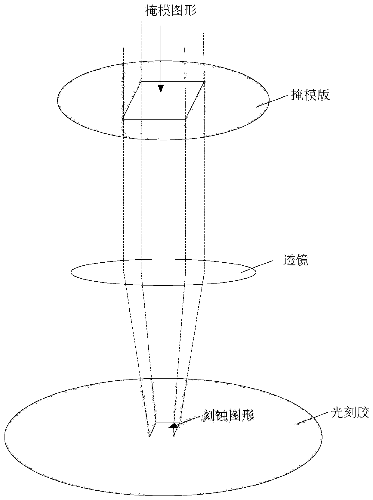
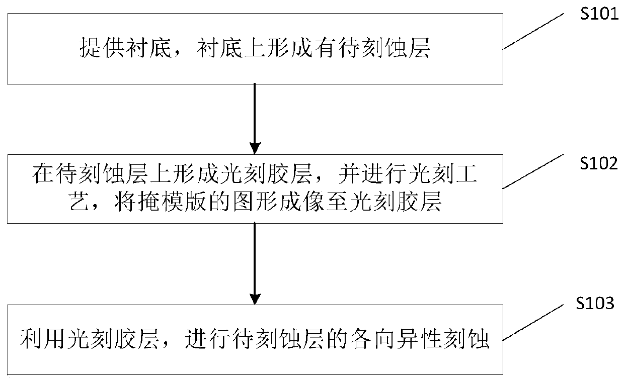
technical field [0001] The present application relates to the field of semiconductor devices and their manufacture, and in particular to a mask and a method for manufacturing semiconductor devices. Background technique [0002] Photolithography technology is one of the key technologies in the field of integrated circuit manufacturing. Specifically, through exposure, the mask pattern on the reticle can be imaged on the object to be processed according to a certain ratio. refer to figure 1 As shown, a mask pattern is formed on the reticle, and the mask pattern is transferred to the photoresist on the surface of the semiconductor substrate by exposure. There is a lens between the reticle and the photoresist, and it is through the lens that the image is formed. The mask pattern is transferred onto the photoresist. [0003] However, when the area ratio of the mask pattern of the designed mask plate is too small, the mask pattern cannot be perfectly transferred to the above the...

Claims


Application Information

Patent Timeline
IPC IPC(8): H01L21/027H01L21/308H01L21/306G03F7/20
CPCG03F7/70283H01L21/0274H01L21/30608H01L21/3086H01L21/3088
Inventor 吴振国徐文超杨超高志虎柳波
Owner YANGTZE MEMORY TECH CO LTD
Why Eureka
Try Eureka