
Permanent magnet motor structure and method capable of detecting permanent magnet demagnetization and rotor eccentricity faults

A technology for rotor eccentric and permanent magnet motors, which is applied to the shape/style/structure of winding conductors, motors, and measuring electronics. It can solve the problems of permanent magnet demagnetization and/or inaccurate detection of rotor eccentricity, and achieve convenient discovery and accuracy. Evaluation, simple operation, high feasibility effect

Active Publication Date: 2019-11-22
HOHAI UNIV
View PDF13 Cites 10 Cited by
  • Summary
  • Abstract
  • Description
  • Claims
  • Application Information

AI Technical Summary

Problems solved by technology

[0005] Aiming at the deficiencies of the prior art, the purpose of the present invention is to provide a permanent magnet motor structure that can detect permanent magnet demagnetization and rotor eccentricity faults, so as to solve the inaccurate detection of permanent magnet demagnetization and / or rotor eccentricity existing in the prior art question

Method used


Image

  • Permanent magnet motor structure and method capable of detecting permanent magnet demagnetization and rotor eccentricity faults
  • Permanent magnet motor structure and method capable of detecting permanent magnet demagnetization and rotor eccentricity faults
  • Permanent magnet motor structure and method capable of detecting permanent magnet demagnetization and rotor eccentricity faults

Examples


Embodiment 1

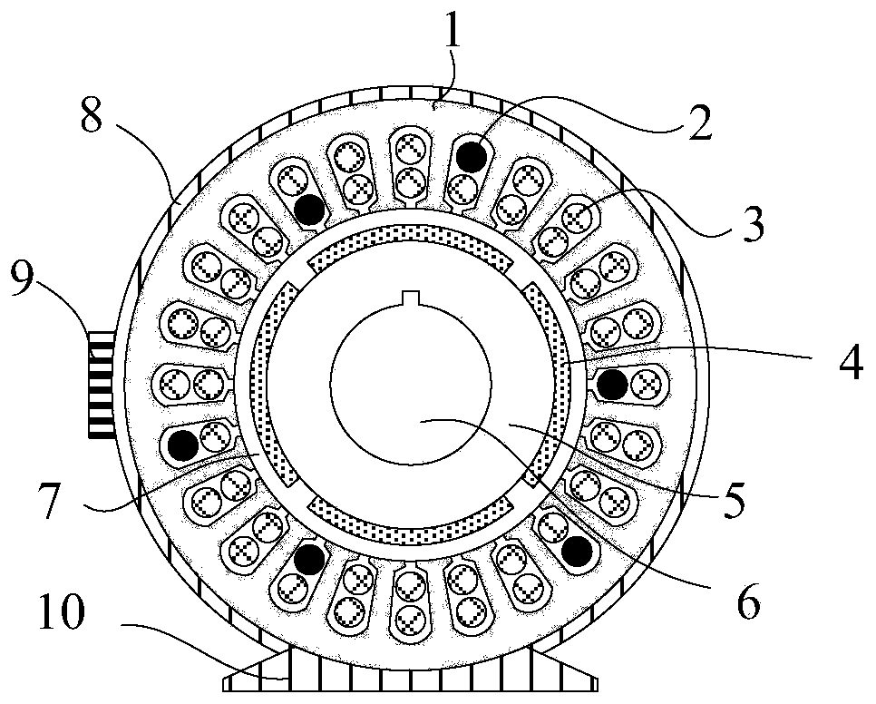
[0040] by figure 1 Take the surface-mounted permanent magnet motor as an example, the motor parameters are: phase number m=3, pole number 2p=4, slot number Q=24, pitch τ=5. Its structure includes: stator core 1, fault detection winding 2, main armature winding 3, permanent magnet pole 4, rotor core 5, rotating shaft 6, air gap 7, casing 8, junction box 9, base 10.

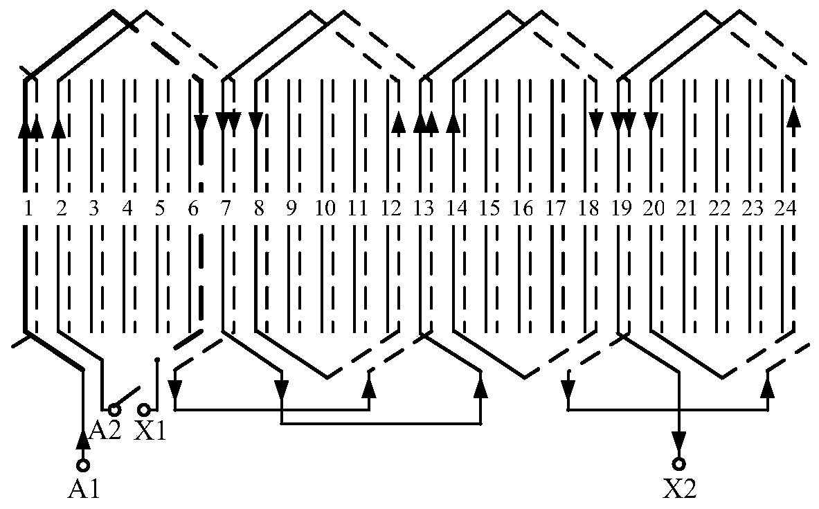
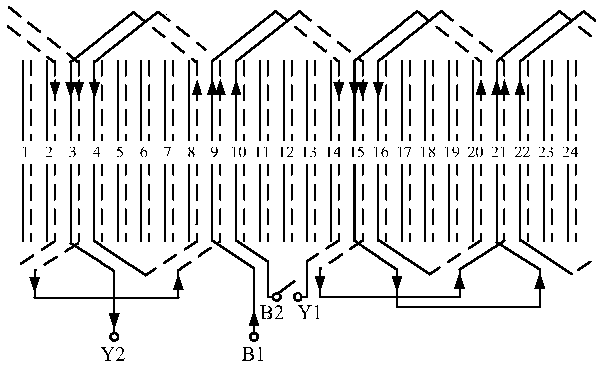
[0041] According to the number of poles of the motor 2p = 4, the number of slots Q = 24 and the pitch τ = 5, the slot number allocation table of the upper side of the three-phase winding can be calculated, as shown in Table 1.

[0042] Table 1 is the slot number allocation table of the upper side of the three-phase winding in the first embodiment

[0043] A Z B X C Y 1st pair of poles 1、2 23、24 9、10 7、8 17、18 15、16 2nd pole 13、14 11、12 21、22 19、20 5、6 3、4

[0044] Among them, the coil under the A-phase belt and the coil under the X-phase belt are recorded as the A-phase w...


PUM


Abstract

The invention discloses a permanent magnet motor structure and method capable of detecting permanent magnet demagnetization and rotor eccentricity faults. The permanent magnet motor structure comprises fault detection windings and main armature windings which are arranged in a crossed mode. The fault detection winding of each phase is only composed of one coil, and the main armature winding can beformed by connecting one or more coils in series. When the motor operates normally, the fault detection winding and the main armature winding are connected in series to perform energy conversion together; when fault detection is carried out, the fault detection winding is disconnected from the main armature winding, the permanent magnet demagnetization and rotor eccentricity conditions of the permanent magnet motor are judged by observing the back electromotive force waveform of the fault detection winding, and the fault is accurately judged. The motor is simple in structure, the fault detection method is convenient to operate, and maintainers can be helped to quickly judge the motor fault type.

Description

technical field [0001] The invention belongs to the field of permanent magnet motors, in particular to a permanent magnet motor structure capable of detecting permanent magnet demagnetization and rotor eccentricity faults. Background technique [0002] The permanent magnet motor is excited by permanent magnets. When the rotor rotates at a synchronous speed, the permanent magnets generate a rotating magnetic field to cut the stator windings and generate back electromotive force. When there is current in the stator winding, the flux linkage interacts with the current to generate electromagnetic torque. Compared with electrically excited motors, permanent magnet motors have no rotor copper loss and higher efficiency, so they are widely used in automotive, aerospace, medical equipment and other fields. [0003] In a permanent magnet motor, the permanent magnet is the magnetic source of the entire motor, which is crucial to the safe operation of the motor. Permanent magnets are...

Claims


Application Information

Patent Timeline
Patent Type & Authority Applications(China)
IPC IPC(8): H02K11/20H02K3/28G01R31/34
CPCH02K11/20H02K3/28G01R31/346Y02T10/64
Inventor 陈浈斐马宏忠刘宝稳李呈营李迅朱硕
Owner HOHAI UNIV
Learn More