
Ignition circuit and gas water heater

An ignition circuit and switching circuit technology, applied in circuits, electrical components, fluid heaters, etc., can solve problems affecting user experience, large discharge noise, etc., and achieve the effects of improving user experience, reducing ignition noise, and increasing on-off frequency.

Pending Publication Date: 2019-11-22
QINGDAO ECONOMIC & TECHN DEV ZONE HAIER WATER HEATER
View PDF0 Cites 0 Cited by
  • Summary
  • Abstract
  • Description
  • Claims
  • Application Information

AI Technical Summary

Problems solved by technology

[0003] In order to solve the technical problem that the pulse igniter is used to ignite the gas in the existing gas water heaters, which produces relatively large discharge noise and affects the user experience, the present invention proposes an ignition circuit, which can solve the above problems

Method used


Image

  • Ignition circuit and gas water heater
  • Ignition circuit and gas water heater
  • Ignition circuit and gas water heater

Examples


Embodiment 1

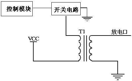
[0022] Embodiment 1, this embodiment proposes an ignition circuit, such as figure 1 As shown, it includes a control module, a switch circuit and at least one transformer. The control signal output terminal of the control module is connected to the control terminal of the switch circuit. The control module outputs a control signal to the switch circuit to control the conduction state of the switch circuit. The switch circuit is connected to Between the primary winding of the transformer and the power supply. In the ignition circuit of this embodiment, the switch circuit is used to control the conduction state of the primary winding of the transformer and the DC power supply. In the conduction state, the secondary winding of the transformer outputs a high-voltage signal according to the above frequency to discharge and ignite. The control module can increase the on-off frequency of the switching circuit to increase the ignition frequency. The total discharge energy remains uncha...

Embodiment 2

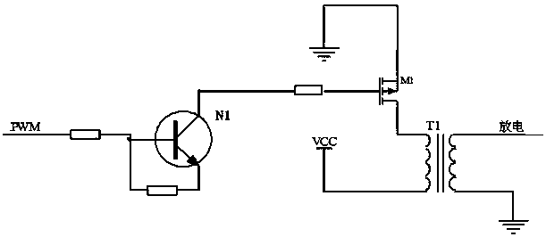
[0031] Embodiment 2. Based on the ignition circuit in Embodiment 1, this embodiment proposes a gas water heater, which includes a fan and the ignition circuit described in Embodiment 1. The fan is connected to a control module. For the specific composition of the ignition circuit, please refer to Embodiment 1 and the attached figure 1 , 2 recorded, and will not be repeated here. It should be noted that after the control module detects that the fan is started, it can output a control command to the ignition circuit for ignition to ensure safe use.

[0032]The gas water heater also includes a water flow detection module arranged in the water inlet pipe or the water outlet pipe, and the water flow detection module is connected with the control module. When it is detected that the water flow exceeds the starting threshold, the control module controls the fan to start, and then outputs a control command to the ignition circuit for ignition.


PUM


Abstract

The invention discloses an ignition circuit. The device comprises a control module, a switching circuit and at least one transformer, wherein a control signal output end of the control module is connected with a control end of the switching circuit, the control module outputs a control signal to the switching circuit to control the conduction state of the switching circuit, and the switching circuit is connected between a primary winding of the transformer and a direct-current power supply. According to the ignition circuit, the switching circuit is used for controlling the conduction state ofthe primary winding of the transformer and the direct-current power supply; the switching circuit is switched on and off according to control frequency output by the control module; the primary winding of the transformer is switched to be in the conduction state with the power supply according to the same frequency, the secondary winding of the transformer correspondingly outputs a high-voltage signal according to the frequency for discharge ignition, the ignition frequency is improved by increasing the on-off frequency of the switching circuit, the single discharge energy is reduced, the ignition noise can be reduced, and the use experience of a user is improved.

Description

technical field [0001] The invention relates to an ignition circuit, in particular to an ignition circuit for a gas water heater. Background technique [0002] At present, gas water heaters use pulse igniters for gas ignition. The discharge frequency of this type of igniter is generally less than 50Hz, the discharge frequency is relatively small, the spark energy of a single discharge is high, and the discharge sound is relatively loud, which causes a lot of discharge noise and affects consumption. The user's comfort. Contents of the invention [0003] In order to solve the technical problem that the pulse igniter is used to ignite the gas in the existing gas water heaters, which produces relatively large discharge noise and affects the user experience, the present invention proposes an ignition circuit, which can solve the above problems. [0004] In order to solve the above-mentioned technical problems, the present invention adopts the following technical solutions to a...

Claims


Application Information

Patent Timeline
IPC IPC(8): H03K7/08H03K17/567H03K17/60H03K17/687F24H9/20
CPCF24H9/2035H03K7/08H03K17/567H03K17/601H03K17/687
Inventor 郑涛王玉刚李键
Owner QINGDAO ECONOMIC & TECHN DEV ZONE HAIER WATER HEATER
Learn More