
Linear driver

A linear driver and wire technology, applied in the direction of connection with control/drive circuits, electric components, transmission devices, etc., can solve the problems of lack of wiring design, unsightly appearance, inconvenient operation, etc.

Active Publication Date: 2019-11-22
LIMOSS (DONGGUAN) CO LTD
View PDF8 Cites 2 Cited by
  • Summary
  • Abstract
  • Description
  • Claims
  • Application Information

AI Technical Summary

Problems solved by technology

[0003] The electrical components in the drive, such as circuit boards, sensors, motors, etc., need to be electrically connected with the power supply or external control components by setting wires. Usually, one end of the wires in the drive housing is welded or plugged into the circuit board in the housing and the other end is Extending out of the housing, the routing section of the wire is wound between the components in the housing, making the layout of the components in the housing messy. If the routing segment falls off, it will affect the normal operation of moving parts, such as worm gear components or moving push rod components. Work
At the same time, there is a lack of wiring design, and the shell of the general driver needs to be equipped with multiple input and output interfaces for the introduction of wires, power terminals, control terminals and lead-in wires, making the overall appearance and structure of the driver complex.
[0004] Moreover, when the existing driver needs to adjust the internal wiring of the driver or replace the wiring rod, the driver's housing can only be disassembled to complete the line adjustment or replace the wire on the circuit board. Drive products with multiple interfaces are cumbersome to use and not beautiful in appearance

Method used


Image

  • Linear driver
  • Linear driver
  • Linear driver

Examples


Embodiment Construction

[0031] In order to make the object, technical solution and advantages of the present invention clearer, the present invention will be further described in detail below in conjunction with the accompanying drawings and embodiments. It should be understood that the specific embodiments described here are only used to explain the present invention, not to limit the present invention.

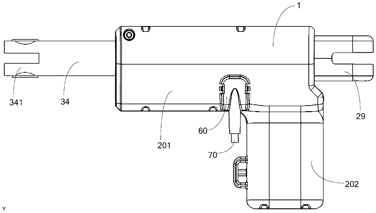
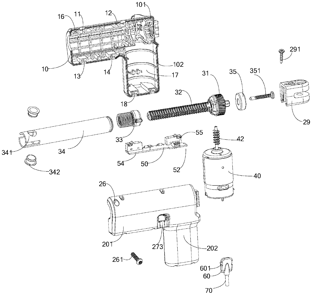
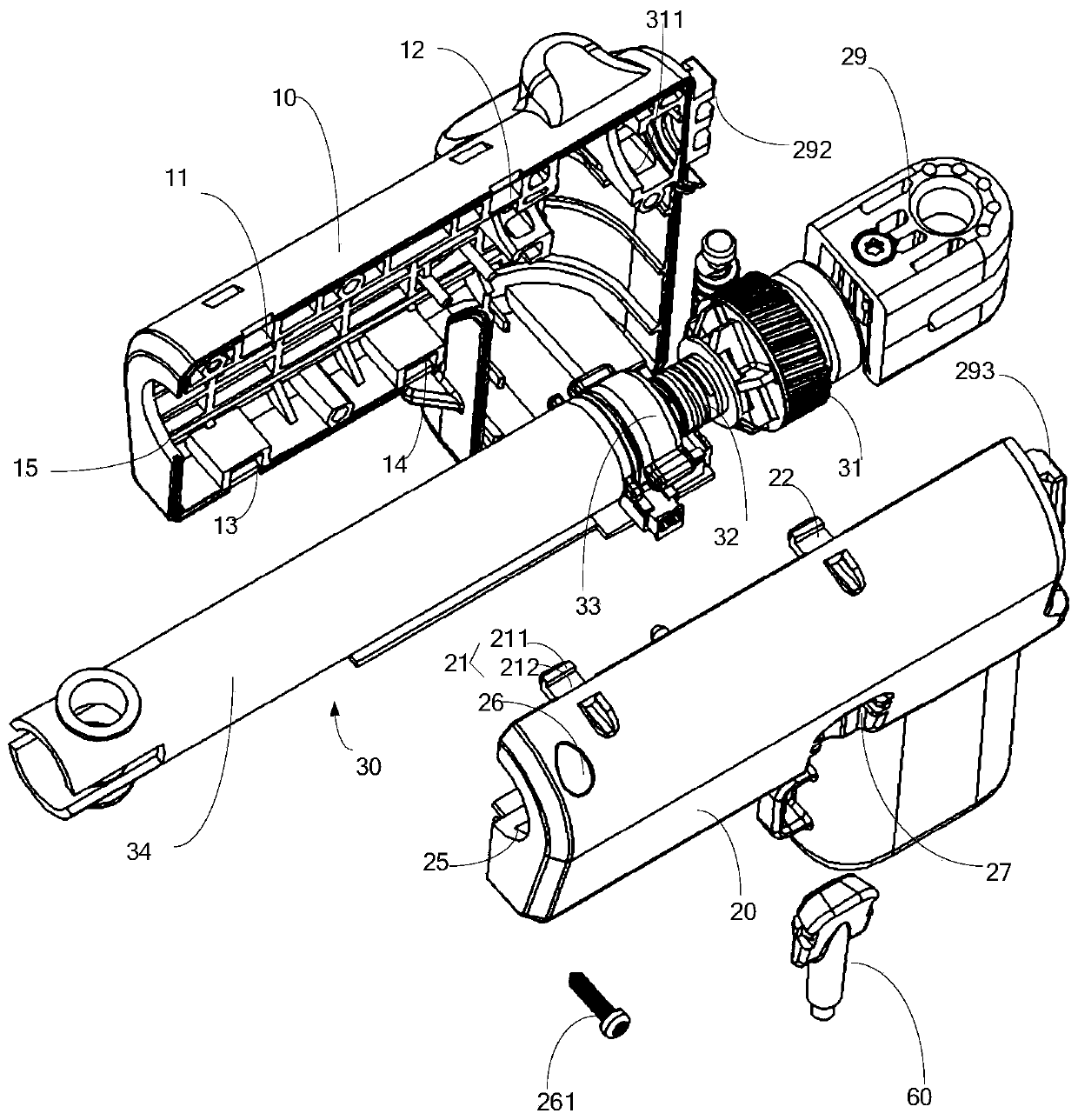
[0032] Please refer to figure 1 and figure 2 , the present invention relates to an improved linear driver. One of the improvements is that the electrical components in the linear driver housing 1 are concentrated on the circuit board. By adding a connecting seat on the circuit board, the connecting terminals are concentrated on the newly added connecting seat. , The housing 1 is provided with an insertion window 273, so that all the wires are placed outside. When applying the linear actuator to a specific device, the wire can be easily replaced according to the specific device requirements. At ...


PUM


Abstract

A linear driver, comprising a housing. A worm assembly, a push rod assembly driven by the worm assembly, a limit switch for limiting the stroke of the push rod assembly, and a motor for driving the worm assembly are mounted in the housing, and a connection base for assembling a connection terminal is provided on the limit switch, the motor is electrically connected to the connection terminal, thehousing is provided with a plug-in window, the plug-in window being aligned with the connection base, and an electric connector of a linear driver bar penetrating through the plug-in window to be plugged on the connection base, and the electric connector and the housing being snap-fitted together by means of a mounting member.

Description

technical field [0001] The invention relates to the field of driving equipment, in particular to a novel linear driver. Background technique [0002] The linear drive is mainly used to convert the rotary motion of the motor into the linear motion or linear reciprocating motion of the push rod. As an executive electric machine, the linear drive can realize remote control, centralized control or automatic control. For example, the driver is used in electric medical beds, electric chairs, electric sofas and other equipment to drive the movable parts of the above equipment to rise or fall. [0003] The electrical components in the driver, such as circuit boards, sensors, motors, etc., need to be electrically connected with the power supply or external control components by setting wires. Usually, one end of the wires in the driver housing is welded or plugged into the circuit board in the housing and the other end is Extending out of the housing, the routing section of the wir...

Claims


Application Information

Patent Timeline
Patent Type & Authority Applications(China)
IPC IPC(8): H02K7/06H01R13/627H01R13/629H01R13/40
CPCH02K7/06H01R13/627H01R13/629H01R13/40H02K7/1166H02K7/145F16H2025/209F16H25/2015F16H2025/2031H02K11/30F16H1/16F16H2025/2046H02K5/225H02K7/116H02K2211/03
Inventor 克里斯汀·伽斯纳
Owner LIMOSS (DONGGUAN) CO LTD
Learn More