
Mechanical automatic cutting device with dust collecting cover

A technology for cutting devices and dust collection hoods, which is applied in metal processing machinery parts, dust removal, chemical instruments and methods, etc., can solve problems affecting environmental sanitation and physical health, and achieve the effect of ensuring reliable operation

Inactive Publication Date: 2019-11-26
YANTAI ENG & TECH COLLEGE YANTAI TECHNICIAN INST
View PDF7 Cites 3 Cited by
  • Summary
  • Abstract
  • Description
  • Claims
  • Application Information

AI Technical Summary

Problems solved by technology

[0004] However, during the working process of the cutting machine, a large amount of debris dust will be generated at the cutting blade, if it is not collected, it will affect environmental sanitation and health

Method used


Image

  • Mechanical automatic cutting device with dust collecting cover
  • Mechanical automatic cutting device with dust collecting cover
  • Mechanical automatic cutting device with dust collecting cover

Examples


Embodiment 1

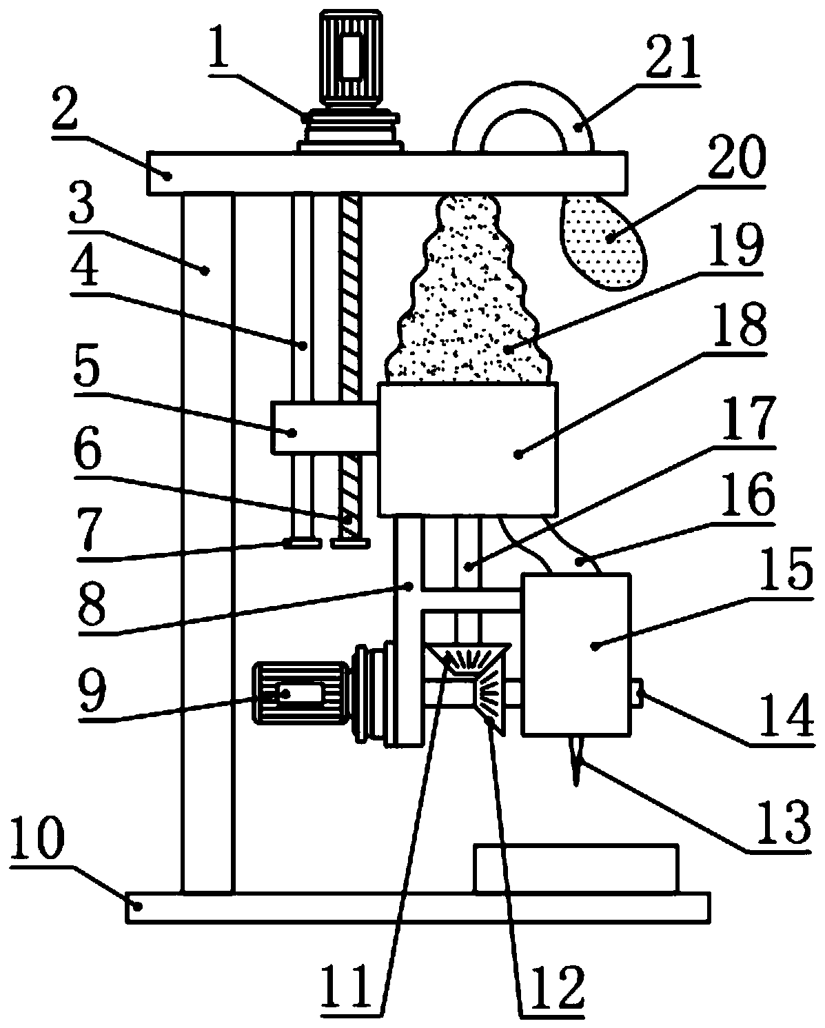
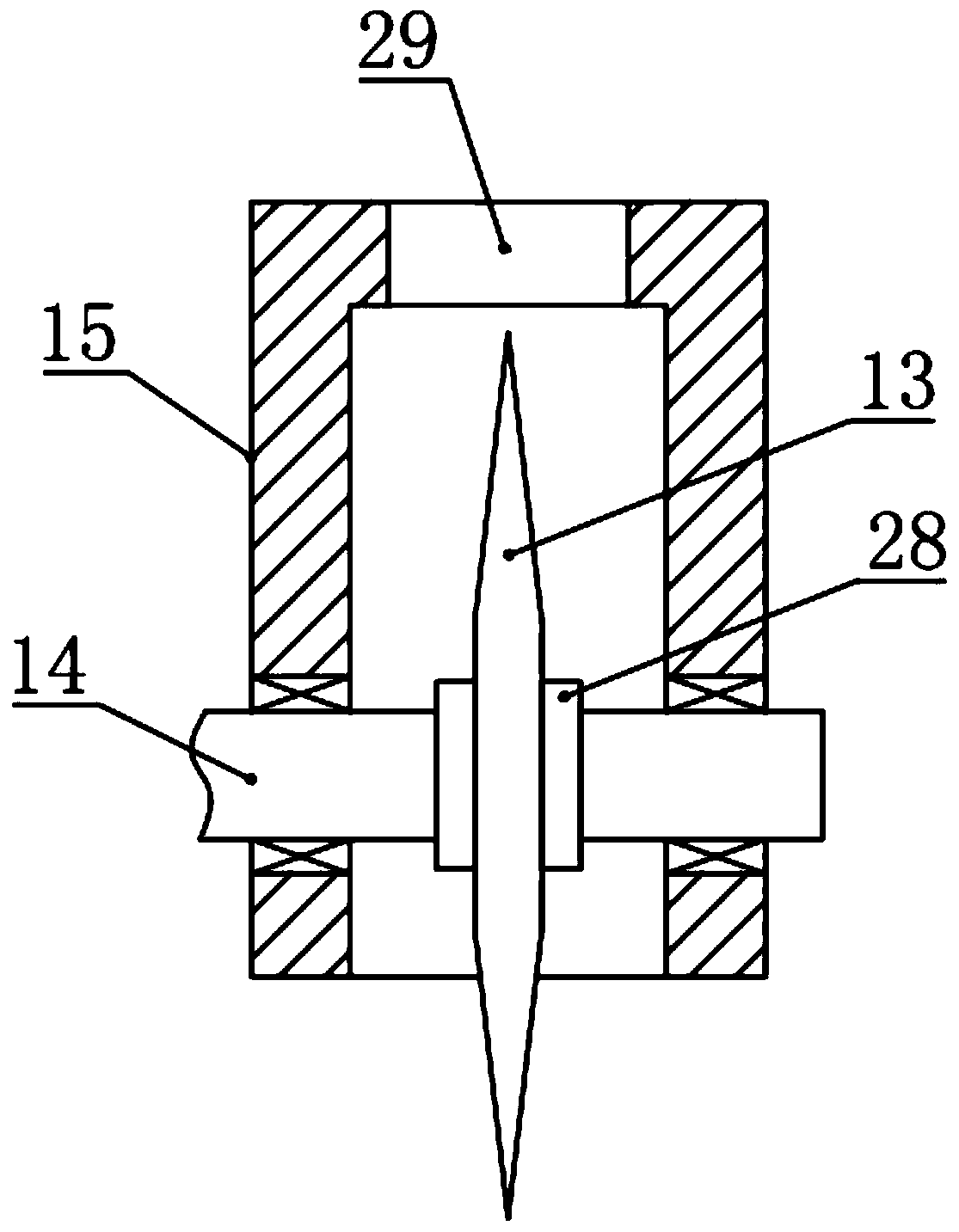
[0033] see Figure 1-4 , in an embodiment of the present invention, a mechanical automatic cutting device with a dust collection cover includes a top frame 2, a column 3, a base 10 and a cutting wheel 13, and the upper and lower ends of the column 3 are respectively fixed with a top frame 2 and the base 10, the underside of the top frame 2 is provided with a dust suction cylinder 18, and the dust suction cylinder 18 is driven to move up and down by a longitudinal drive device arranged on the top frame 2, and the bottom side of the dust suction cylinder 18 passes through the fixed frame 8 Support is fixed with horizontal shaft 14, and horizontal shaft 14 is driven to rotate by second motor 9, and cutting wheel 13 is installed on the horizontal shaft 14, and the outer cover of described cutting wheel 13 is provided with dust collection cover 15, and dust collection cover 15 is fixed with The frame 8 is fixedly connected, and the dust collection cover 15 is connected with the dus...

Embodiment 2

[0038] see Figure 1-2 , the difference between this embodiment and embodiment 1 is:

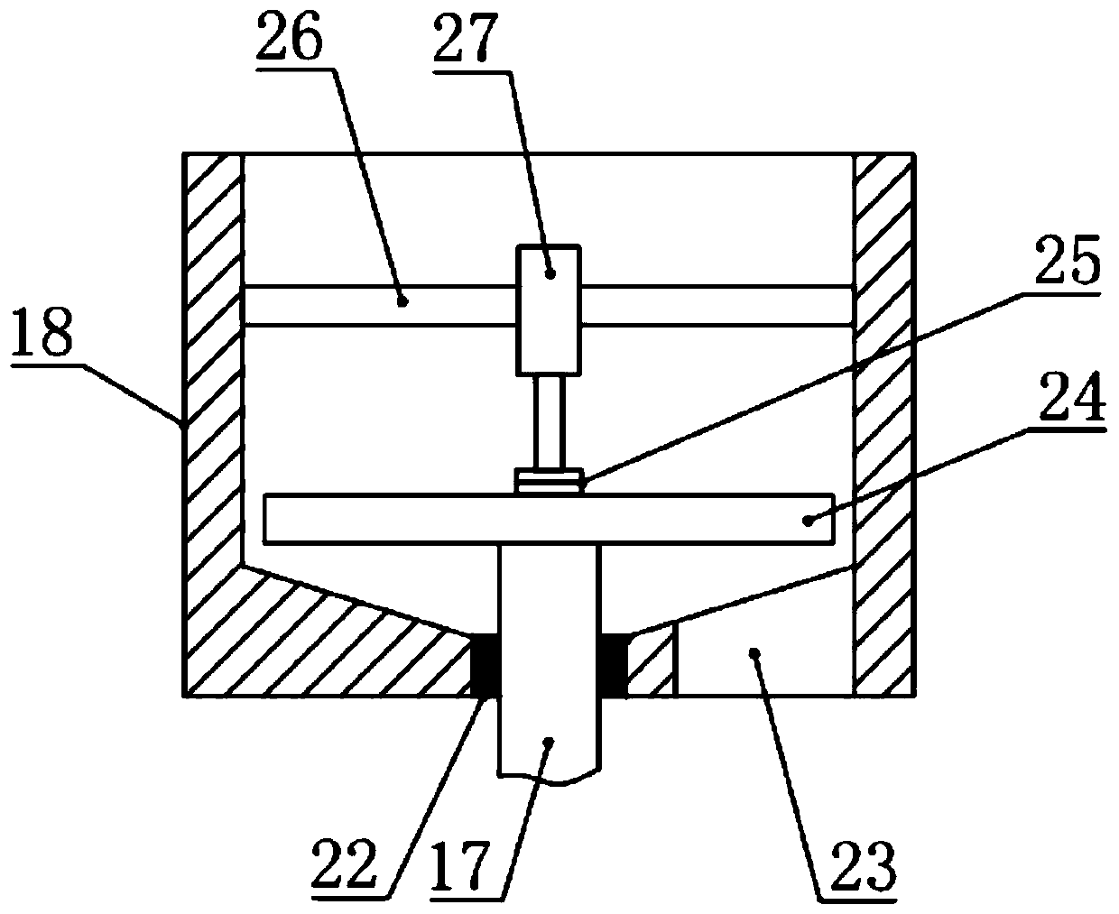
[0039] In this embodiment, the dust suction mechanism includes a first bevel gear 11, a second bevel gear 12, a vertical shaft 17, a fan blade 24, a rotating body 25, a cross bracket 26 and a telescopic cylinder 27, and the dust suction cylinder 18 is The upper opening of the cylindrical barrel, the bottom of the inner cavity of the dust suction cylinder 18 is a conical structure with the outer ring upturned, which is beneficial to dust collection. The bottom of 18 is also provided with a sliding sleeve 22 that cooperates with the vertical shaft 17. The vertical shaft 17 can rotate relative to the sliding sleeve 22 and move longitudinally. The fan blade 24 that sucks the air in the inner chamber of the vacuum tube 18 from bottom to top is installed and fixed on the upper end of the vertical shaft 17. The structure of the fan blade 24 can adopt the existing technology. Installed and fixed o...


PUM


Abstract

The invention relates to the field of cutting devices, in particular to a mechanical automatic cutting device with a dust collecting cover. The mechanical automatic cutting device comprises a top frame, a stand column, a base and a cutting wheel. A dust suction cylinder is arranged on the lower side of the top frame and is driven by a longitudinal driving device arranged on the top frame to move up and down. A cross shaft is supported and fixed to the lower side of the dust suction cylinder through a fixing frame and is driven by a second motor to rotate. The cutting wheel is arranged on the cross shaft. A dust collection cover is arranged on the outer side of the cutting wheel in a covering manner, is fixedly connected with the fixing frame, and is further connected with the dust suctioncylinder through a connecting pipe. The dust suction cylinder is further provided with a dust suction mechanism which can be in control linkage fit with the cross shaft. The top of the dust suction cylinder is further connected with a telescopic corrugated cylinder. The telescopic corrugated cylinder is connected with a dust collection cloth bag through an inverted U-shaped pipe. According to themechanical automatic cutting device, through the selective matching of dust removal and cutting linkage, dust generated during cutting can be removed while cutting, the energy is saved, the environment is protected, and the health of workers is facilitated.

Description

technical field [0001] The invention relates to the field of cutting devices, in particular to a mechanical automatic cutting device with a dust collecting cover. Background technique [0002] With the development of modern mechanical processing industry, the requirements for cutting quality and precision are constantly improving, and the requirements for improving production efficiency, reducing production costs, and highly intelligent automatic cutting functions are also increasing. The development of CNC cutting machines must adapt to the requirements of the development of modern machining industry. Cutting machine is divided into flame cutting machine, plasma cutting machine, laser cutting machine, water cutting and so on. [0003] In the process of mechanical processing, the common methods of plate cutting include manual cutting, semi-automatic cutting machine cutting and CNC cutting machine cutting. Compared with manual and semi-automatic cutting methods, CNC cutting...

Claims


Application Information

Patent Timeline
Patent Type & Authority Applications(China)
IPC IPC(8): B26D7/18B08B15/04B23Q11/00
CPCB08B15/04B23Q11/0046B26D7/1863
Inventor 苏慧祎于海青刘爱荣张士印巩华荣
Owner YANTAI ENG & TECH COLLEGE YANTAI TECHNICIAN INST
Learn More