Concrete processing equipment

A technology for processing equipment and concrete, which is applied to clay preparation devices, solid separation, filtration and screening, etc. It can solve problems such as unsatisfactory demands, and achieve the effects of saving resources, fully mixing, and improving quality

Inactive Publication Date: 2019-11-26
郭倩
View PDF10 Cites 23 Cited by
  • Summary
  • Abstract
  • Description
  • Claims
  • Application Information

AI Technical Summary

Problems solved by technology

[0003] At present, in the process of concrete processing, the raw materials are directly added to the mixing tank, and the mixing rod in the mixing tank is used to mix and process the raw materials. However, with the improvement of construction quality requirements, it is necessary to improve the quality of concrete. The method of pouring raw materials into the mixing tank and stirring through the stirring rod obviously cannot meet the demand. Therefore, in view of the above status quo, it is urgent to develop a concrete processing equipment to overcome the shortcomings in current practical applications.

Method used


Image

  • Concrete processing equipment
  • Concrete processing equipment
  • Concrete processing equipment

Examples


Embodiment 1

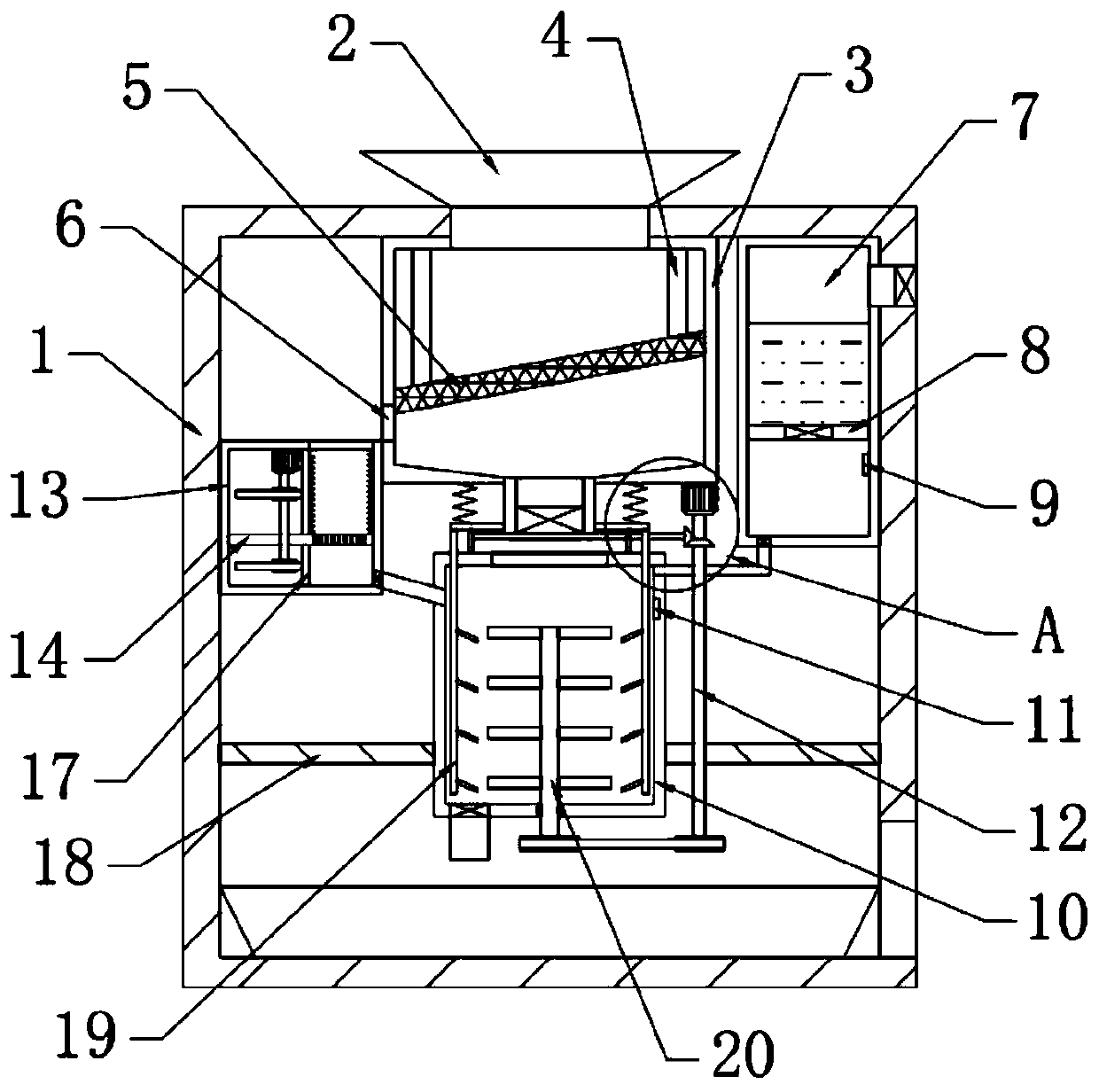
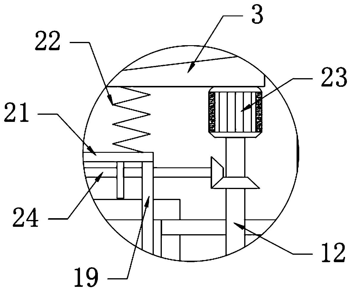
[0026] see Figure 1~3 , in an embodiment of the present invention, a concrete processing equipment includes a casing 1, a feed hopper 2 is arranged on the top of the casing 1, a screen box 3 is arranged on the lower side of the feed hopper 2, and the screen box 3 It is fixedly connected with the housing 1, the left side of the screen box 3 is provided with a gravel processing mechanism fixedly connected with the housing 1, and the lower side of the screen box 3 is provided with a fixed plate 18 fixedly connected with the housing 1. A mixing bucket 10 is fixedly connected on the fixed plate 18, and the mixing bucket 10 is connected with the gravel processing mechanism through a conduit. Connected by a water inlet pipe, a material storage box is provided on the lower side of the mixing bucket 10 .

Embodiment 2

[0028] In this embodiment, a sieve plate 5 is installed obliquely on the inner side of the sieve box 3, and the sieve plate 5 is slidingly connected with the sieve box 3. The vibrating rod 4 that moves repeatedly, the other end of the vibrating rod 4 is fixedly connected with the screen box 3, the left side of the screen box 3 is provided with a discharge port 6, and the bottom of the screen box 3 is fixedly connected with a discharge port. The sieve box 3 is provided to screen impurities such as crushed stones in the raw materials, so that the raw materials falling into the mixing tank 10 are finer sand, which is beneficial to improve the quality of the concrete produced.

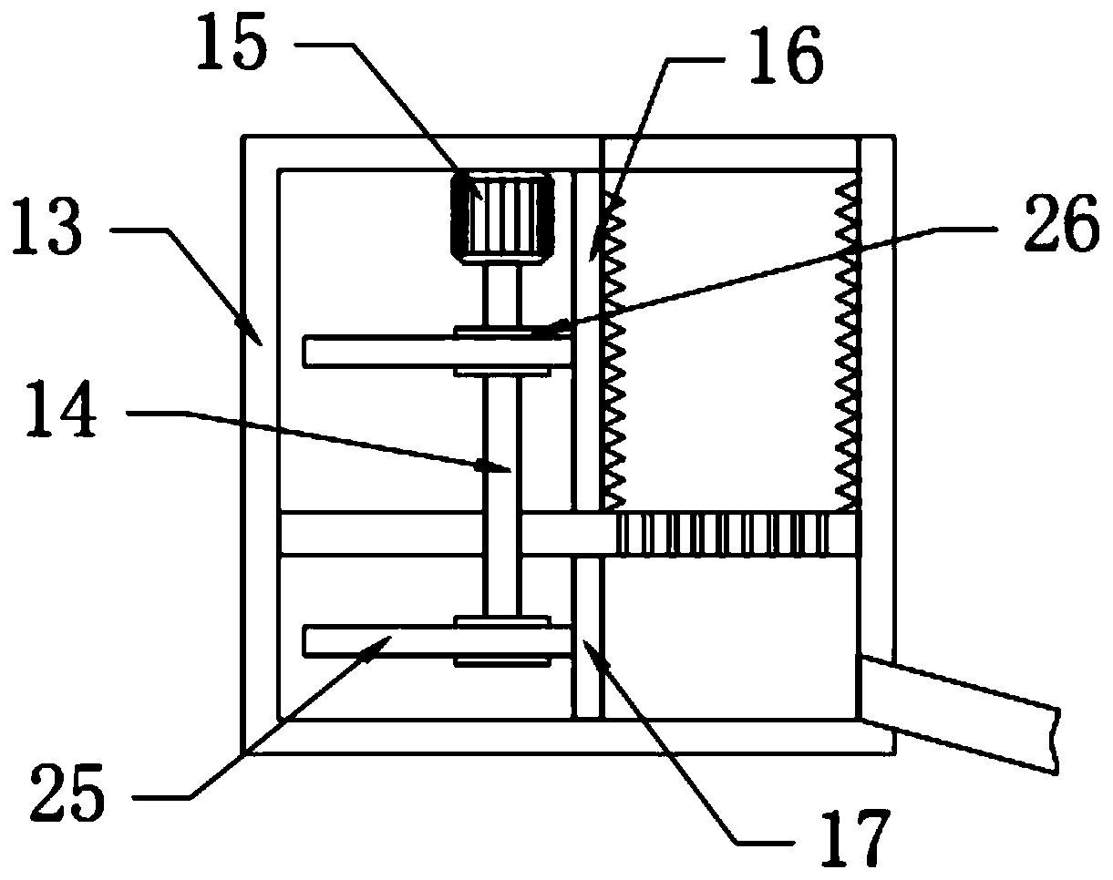
[0029] In this embodiment, the gravel processing mechanism includes a casing 13, a horizontal plate 14, a pressing plate 16 and a push plate 17, the casing 13 is arranged on the left side of the screen box 3, the casing 13 is fixedly connected with the casing 1, and the The inner side of the casing 13 is f...


PUM


Abstract

The invention relates to the technical field of construction, in particular to concrete processing equipment. The concrete processing equipment comprises a housing; the top of the housing is providedwith a feed hopper; the lower side of the feed hopper is provided with a screening box; the left side of the screening box is provided with a gravel processing mechanism; the lower side of the screening box is provided with a fixed plate which is fixedly connected with the housing; the fixed plate is fixedly connected with a stirring bucket; a water tank is arranged at the right side of the screening box; and a storage box is arranged at the lower side of the stirring bucket. According to the concrete processing equipment, the screening box is used for screening impurities such as gravel existing in a raw material so that the raw material falling into the stirring bucket is finer sand, the quality of the prepared concrete is beneficially improved; by arranging the gravel processing mechanism, the screened stone pieces can be crushed so that the stone pieces can be reutilized; by arranging a partition plate, a liquid level sensor and an infrared sensor, the amount of water and raw material added into the stirring bucket can be accurately controlled; and thus the ratio of the raw material to water is effectively controlled.

Description

technical field [0001] The invention relates to the technical field of construction, in particular to concrete processing equipment. Background technique [0002] Concrete is a commonly used building material, which is made by mixing sandstone, cementitious material and mud. It needs to be mixed by mixing settings to make the ingredients in the concrete mix evenly. [0003] At present, in the process of concrete processing, the raw materials are directly added into the mixing tank, and the mixing rods in the mixing tank are used to mix and process the raw materials. However, with the improvement of construction quality requirements, it is necessary to improve the quality of concrete. The method of pouring raw materials into the mixing tank and stirring through the stirring rod obviously cannot meet the demand. Therefore, in view of the above status quo, it is urgent to develop a concrete processing equipment to overcome the shortcomings in current practical applications. C...

Claims


Application Information

Patent Timeline
Patent Type & Authority Applications(China)
IPC IPC(8): B28C5/16B28C7/06B28C7/12B07B1/34B02C1/14B02C23/08
CPCB02C1/14B02C23/08B07B1/343B28C5/16B28C7/067B28C7/122B28C7/128
Inventor 不公告发明人
Owner 郭倩
Why Eureka
Try Eureka