A water-cooled parallel flow heat exchanger with flat tubes connected
A parallel flow heat exchanger and heat exchanger technology, applied in the field of heat exchange, can solve the problems of low heat exchange efficiency, and achieve the effect of increasing the moving path, good exchange effect, and convenient installation and disassembly
- Summary
- Abstract
- Description
- Claims
- Application Information
AI Technical Summary
Problems solved by technology
Method used
Image

Examples
Embodiment 1
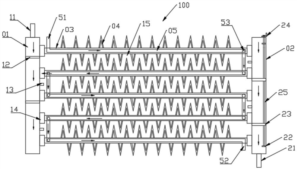
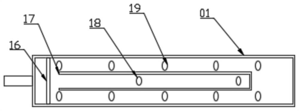
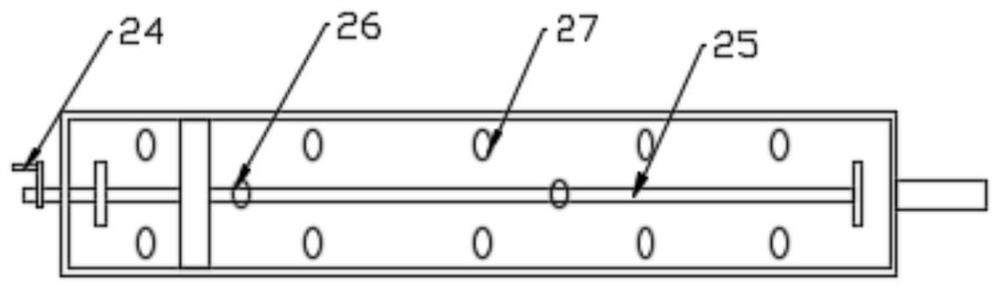
[0028] see Figure 1~3 , in an embodiment of the present invention, a water-cooled parallel-flow heat exchanger with flat tubes in a row includes a first heat exchanger 100, and the first heat exchanger 100 is used to exchange heat for air; the first heat exchanger The device 100 includes a first header 01 and a second header 02, through which the circulation of air is facilitated, and heat is exchanged during the circulation of the air.
[0029] The installation pipe 14 is fixed on the first header 01 and the second header 02, and the installation pipe 14 is detachably connected with the flat pipe 03, which facilitates the installation and disassembly of the flat pipe 03, and the flat pipe 03 is used for air circulation , when the hot air circulates in the flat tubes 03, heat exchange is carried out; the number of the flat tubes 03 is multiple, and the residence time of the hot air in the flat tubes 03 can be improved by arranging a plurality of flat tubes 03, thereby obtaini...
Embodiment 2
[0035] see Figure 4~5 The difference between this embodiment of the present invention and Embodiment 1 is that a spoiler assembly 06 is also provided on the flat tube 03, and the heat exchange efficiency is improved through the spoiler assembly 06; the spoiler assembly 06 includes The lap pipe 62 on 03, the lap pipe 62 communicates with the flat pipe 03 at both ends respectively, the lap pipe 62 is provided with a rotating shaft 65, that is, the rotating shaft 65 runs through all the lap pipes 62, and the rotating shaft 65 is located in the lap pipe 62 A fixed sleeve 63 is provided, and the fixed sleeve 63 is provided with a stirring rod 64. When the rotating shaft 65 rotates, it can drive the fixed sleeve 63 to rotate, and then drive the stirring rod 64 to rotate, and the cooling water in the lap pipe 62 Cooling is very simple. At the same time, one end of the overlapping pipe 62 is fixed to the output shaft of the motor 61, and then the motor 61 drives the rotating shaft 65...
Embodiment 3
[0037] see Figure 6-8 , a second heat exchanger 200 and a third heat exchanger 300 are also provided below the first heat exchanger 100, the first heat exchanger 100, the second heat exchanger 200 and the third heat exchanger 300 are identical, And between the first heat exchanger 100 and the second heat exchanger 200, and between the second heat exchanger 200 and the third heat exchanger 300 are fixed by the backing plate 07 to improve the stability of the three; at the same time, the first The heat exchanger 100 and the third heat exchanger 300 are respectively fixed with the first assembly 81 and the third assembly 83, and the second heat exchanger 200 is fixed with the second assembly 82, and the two ends of the second assembly 82 are provided with There are protrusions 84, and the protrusions 84 are inserted into the grooves 85 on the first assembly 81 and the third assembly 83, and the first heat exchanger 100, the second heat exchanger 200, and the Three heat exchange...
PUM
 Abstract
Description
Claims
Application Information
 - R&D
- Intellectual Property
- Life Sciences
- Materials
- Tech Scout
- Unparalleled Data Quality
- Higher Quality Content
- 60% Fewer Hallucinations
Browse by: Latest US Patents, China's latest patents, Technical Efficacy Thesaurus, Application Domain, Technology Topic, Popular Technical Reports.
© 2025 PatSnap. All rights reserved.Legal|Privacy policy|Modern Slavery Act Transparency Statement|Sitemap|About US| Contact US: help@patsnap.com