Eureka AIR delivers breakthrough ideas for toughest innovation challenges, trusted by R&D personnel around the world.

Test system and ground test method of ultra-short wave orientation device

A test system and ground test technology, applied in the field of avionics measurement and control, can solve problems such as time-consuming and labor-intensive, poor signal reception, complicated debugging, etc., to reduce flight risk and pressure, shorten fault diagnosis cycle, and reduce flight risk.

Active Publication Date: 2019-11-26
XIAN AIRCRAFT IND GROUP
View PDF26 Cites 8 Cited by
  • Summary
  • Abstract
  • Description
  • Claims
  • Application Information

AI Technical Summary

Problems solved by technology

[0005] 1) Test blank: Due to the complex working principle of the airborne automatic orientation system and the specific pertinence of the ultrashort wave orientation instrument, there is no ground single test and system joint debugging method specifically for the ultrashort wave orientation instrument. The equipment and signal source cooperate with the test, the cost is high, and the debugging is relatively complicated and the efficiency is low
[0006] 2) Environmental constraints: When the aircraft is in a static state on the ground, it only provides static position information, but cannot enter the dynamic navigation mode, and cannot restore the real flight environment; at the same time, the limitations of static detection make the detection results more affected by the geographical location and surrounding buildings. Large, prone to poor signal reception, signal loss, etc., it is difficult to completely verify system performance
[0007] 3) Inconvenient monitoring: For the RS422 bus signal in the workflow of the ultrashort wave directional instrument, when it is necessary to measure its data information, the traditional environment does not have redundant monitoring channels, and it cannot be measured as required. It can only be estimated or re-divided for measurement, which is time-consuming strong and imprecise

Method used


Image

  • Test system and ground test method of ultra-short wave orientation device

Examples


Embodiment Construction

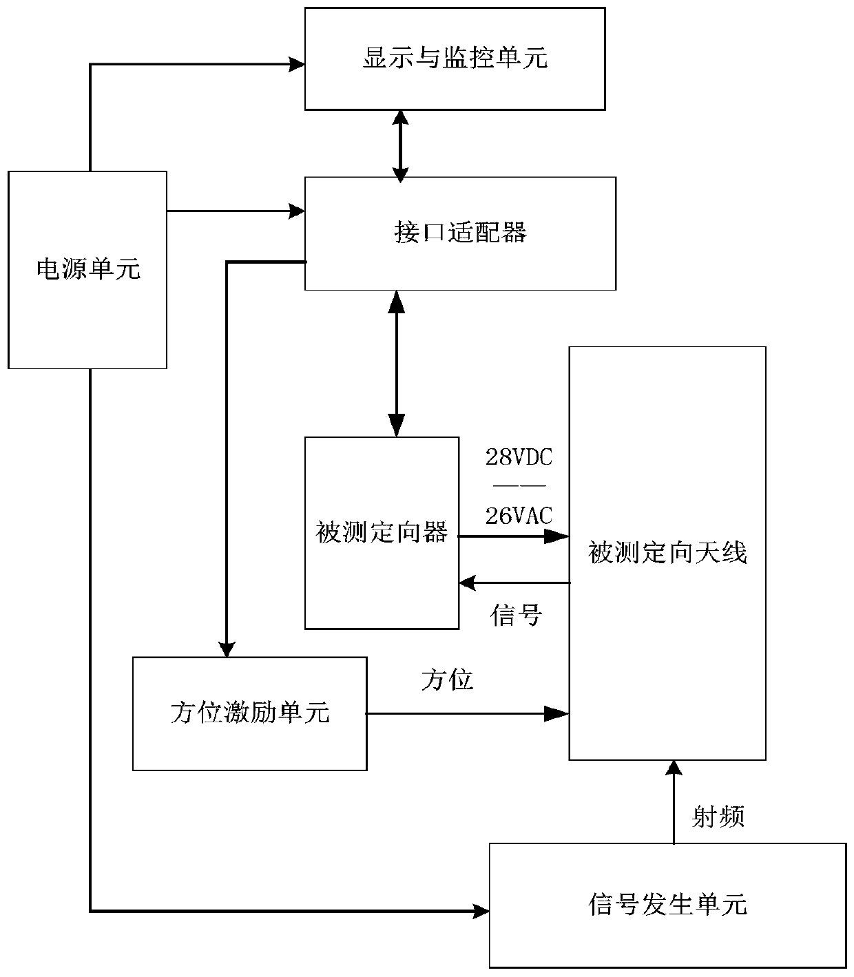
[0033] like figure 1 As shown in the figure, a test system for ultrashort wave directional instrument, including power supply, display and monitoring unit, azimuth excitation unit, signal generation unit, interface adapter, the power supply supplies power for other units in the test system and the ultrashort wave directional instrument to be tested; the power supply also has an external The power supply interface can be used separately from the test system for field troubleshooting and avionics joint test. The display and monitoring unit simulates the integrated control display and modifies the parameters of the tested ultrashort wave directional instrument according to the needs, and simulates the flight instrument to display the directional orientation of the tested ultrashort wave directional instrument; the azimuth excitation unit simulates and outputs eight kinds of relative orientations in the air: 0°, 45° , 90°, 135°, 180°, 225°, 270°, 315°, and simulate radiation targe...


PUM


Abstract

The invention discloses a test system and a ground test method of an ultra-short wave orientation device. The test system comprises a power supply, a display and monitoring unit, an orientation excitation unit, a signal generation unit and an interface adapter. According to the test method, with the test system as a platform, the electrical performance technical indexes of the ultra-short wave orientation device can be tested and verified to check whether information such as the orientation and frequency meets requirements is checked, so that whether the air-to-air orientation function of theultra-short wave orientation device is qualified is determined. With the test system and the ground test method, signal input in all air-to-air directions is simulated on the ground and the real flight environment is simulated without being limited by the field or position, so that a technical problem of limitation of environmental factors or navigation systems is solved.

Description

technical field [0001] The invention relates to the technical field of avionics measurement and control, in particular to a test system and a ground test method for an ultrashort wave directional instrument. Background technique [0002] The ultrashort wave direction finder includes a directional antenna and a directional device, which can continuously track and orient radio incoming waves and provide relevant azimuth information. The directional antenna receives the radio frequency signal transmitted from a certain direction in the space. After the radio frequency signal is modulated by the directional antenna and processed by the directional device, it outputs the azimuth angle signal that meets the requirements of the RS422 bus interface, and sends it to the integrated control display and flight instrument for display. At the same time, the integrated control display can control the working frequency and self-checking status of the orientation instrument through the RSS42...

Claims


Application Information

Patent Timeline
IPC IPC(8): G01S3/02G01R31/00
CPCG01S3/026G01R31/00Y02D30/70
Inventor 杜洋黄平安韩冰宇峰
Owner XIAN AIRCRAFT IND GROUP
Why Eureka
Eureka Blog
Learn More