A stamping equipment

A stamping equipment and stamping technology, which is applied in metal processing equipment, feeding devices, manufacturing tools, etc., can solve the problems of lower production efficiency of rotors, achieve the effects of reducing scratches, reducing debugging time, and improving stability

Inactive Publication Date: 2020-12-04
温岭市汇强机电股份有限公司
View PDF12 Cites 0 Cited by
  • Summary
  • Abstract
  • Description
  • Claims
  • Application Information

AI Technical Summary

Problems solved by technology

[0004] The above-mentioned existing technical solutions have the following defects: However, after the scraps are punched and dropped from the strips, it is impossible to continuously feed a number of scraps into the trimming stamping die by the strip feeding method again, and manual work is required one by one. Feeding, resulting in a reduction in the production efficiency of the rotor

Method used


Image

  • A stamping equipment
  • A stamping equipment
  • A stamping equipment

Examples


Embodiment Construction

[0040] The present invention will be described in further detail below in conjunction with the accompanying drawings.

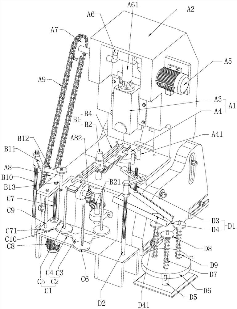
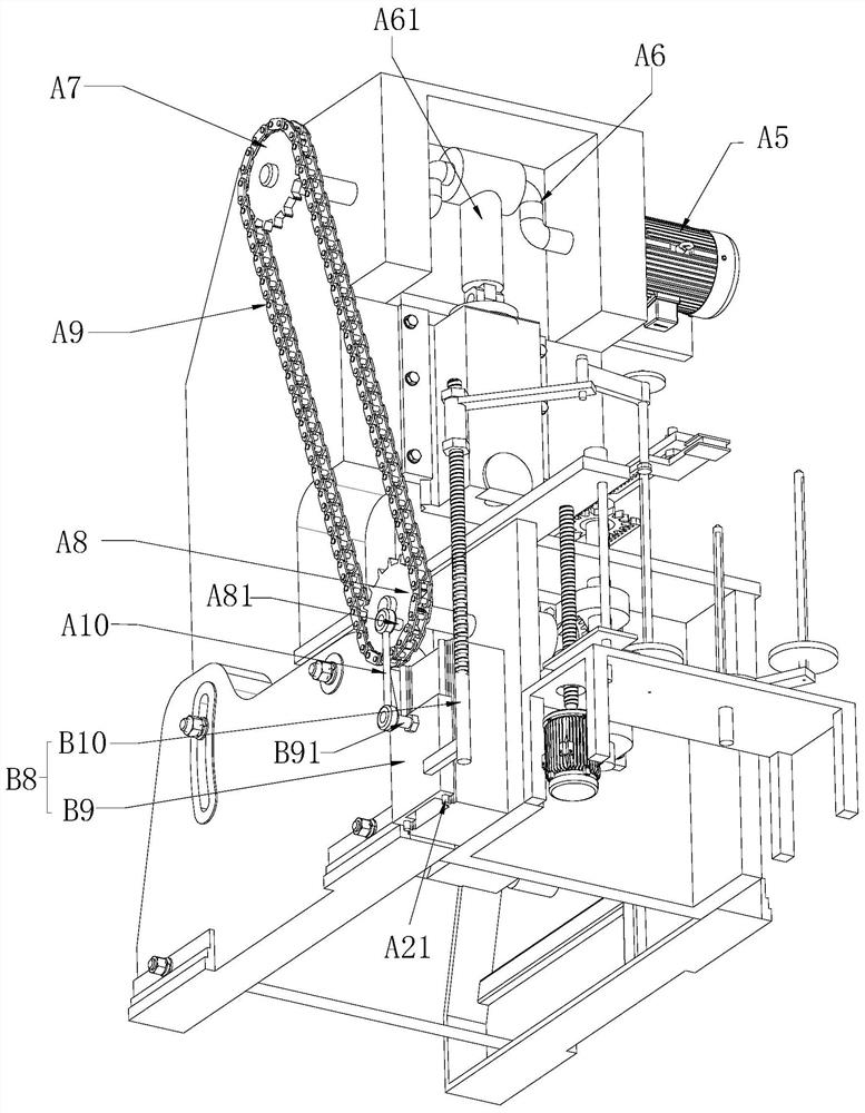
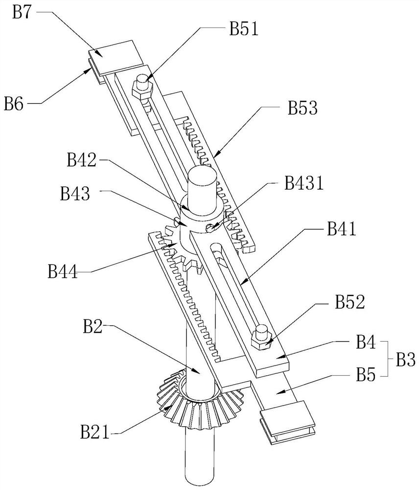
[0041] Such as figure 1 As shown, a sheet stamping equipment includes a storage unit C1, a punching unit A1, and a receiving unit D1 arranged in sequence along the moving path of the waste, wherein the storage unit C1 allows the waste to be stacked in the vertical direction, and the punching unit A1 includes Stamping frame A2, the upper die assembly A3 and the lower die assembly A4 arranged on the punching frame A2, the upper die assembly A3 is provided with a magnet one, when the upper die assembly A3 and the lower die assembly A4 cooperate , the convex line is cut off, and the material plate is adsorbed to the upper membrane assembly, and a transfer unit B1 is set on the stamping frame A2, and the transfer unit B1 moves the waste materials stacked in the storage unit C1 to the lower assembly one by one, and The material sheet in the upper membrane assembly...


PUM


Abstract

The invention relates to punched sheet punching equipment which comprises a punching unit, wherein the punching unit comprises a punching rack, an upper die assembly and a lower die assembly; the upper die assembly and the lower die assembly are arranged on the punching rack; a magnet I used for adsorbing a material plate is arranged in the upper die assembly; a transfer unit is arranged on the punching rack, and comprises a transfer shaft and a transfer rod; the transfer shaft extends in the vertical direction; the transfer rod is arranged at the upper end of the transfer shaft and extends inthe horizontal direction; magnets II are fixed on the lower sides of two ends of the transfer rod; magnets III are fixed on the upper sides of the two ends of the transfer rod; the magnetism of the magnets III is greater than that of the magnet I; the end part of the transfer rod rotates and passes through a position above a material supporting plate and a position above the lower die assembly; material blocking rods are arranged in the lower die assembly; the upper ends of the material blocking rods are propped against waste at the lower end of the transfer rod; and the waste drops into thelower die assembly. Through the transfer rod, the material feeding and unloading actions can be continuously completed by utilizing time intervals for the cooperation between the upper die assembly and the lower die assembly; the processing efficiency can be improved; and furthermore, the material plate can be protected, the scratching phenomenon can be reduced, and the rotor quality in the laterstage can be improved.

Description

technical field [0001] The invention relates to the technical field of rotor production equipment, in particular to a piece of stamping equipment. Background technique [0002] The fixed part of the motor is called the stator, on which a pair of stationary main magnetic poles with DC excitation are installed; while the rotating part in the stator is called the rotor, on which the armature winding is installed, and the induced electromotive force is generated after electrification, acting as Rotate the magnetic field, and then generate electromagnetic torque for energy conversion. [0003] Currently, when producing paired stator and rotor punching sheets, the strip material is fed into the stator stamping die, the stator punching sheet is punched on the strip material, and waste is formed in the middle of the stator punching sheet, and the waste material includes the middle circular one. The material plate and the convex lines distributed on the material plate at intervals i...

Claims


Application Information

Patent Timeline
IPC IPC(8): B21D28/02B21D43/18B21D43/22H02K15/02
CPCB21D28/02B21D43/18B21D43/22H02K15/02
Inventor 周庆君
Owner 温岭市汇强机电股份有限公司
Why Eureka
Try Eureka