Supercharge Your Innovation With Domain-Expert AI Agents!

Reactive compensation method and device for medium-voltage network and computer readable storage medium

A compensation method and medium-voltage technology, applied in reactive power compensation, reactive power adjustment/elimination/compensation, etc., can solve the problems of large power supply network loss, unreasonable reactive power compensation, and complex power supply network structure in urban rail transit systems. , to achieve the effect of saving transformation costs and reasonable reactive power compensation results

Active Publication Date: 2019-11-29
BEIJING QIANSIYU ELECTRIC
View PDF10 Cites 2 Cited by
  • Summary
  • Abstract
  • Description
  • Claims
  • Application Information

AI Technical Summary

Problems solved by technology

[0004] The present disclosure provides a reactive power compensation method, device, and computer-readable storage medium for a medium-voltage network to solve the problem of adding reactive power compensation equipment to an urban rail transit system in the prior art, which causes the power supply network structure of the urban rail transit system to be complicated. Complicated, unreasonable reactive power compensation, large power supply network loss

Method used


Image

  • Reactive compensation method and device for medium-voltage network and computer readable storage medium
  • Reactive compensation method and device for medium-voltage network and computer readable storage medium
  • Reactive compensation method and device for medium-voltage network and computer readable storage medium

Examples


Embodiment Construction

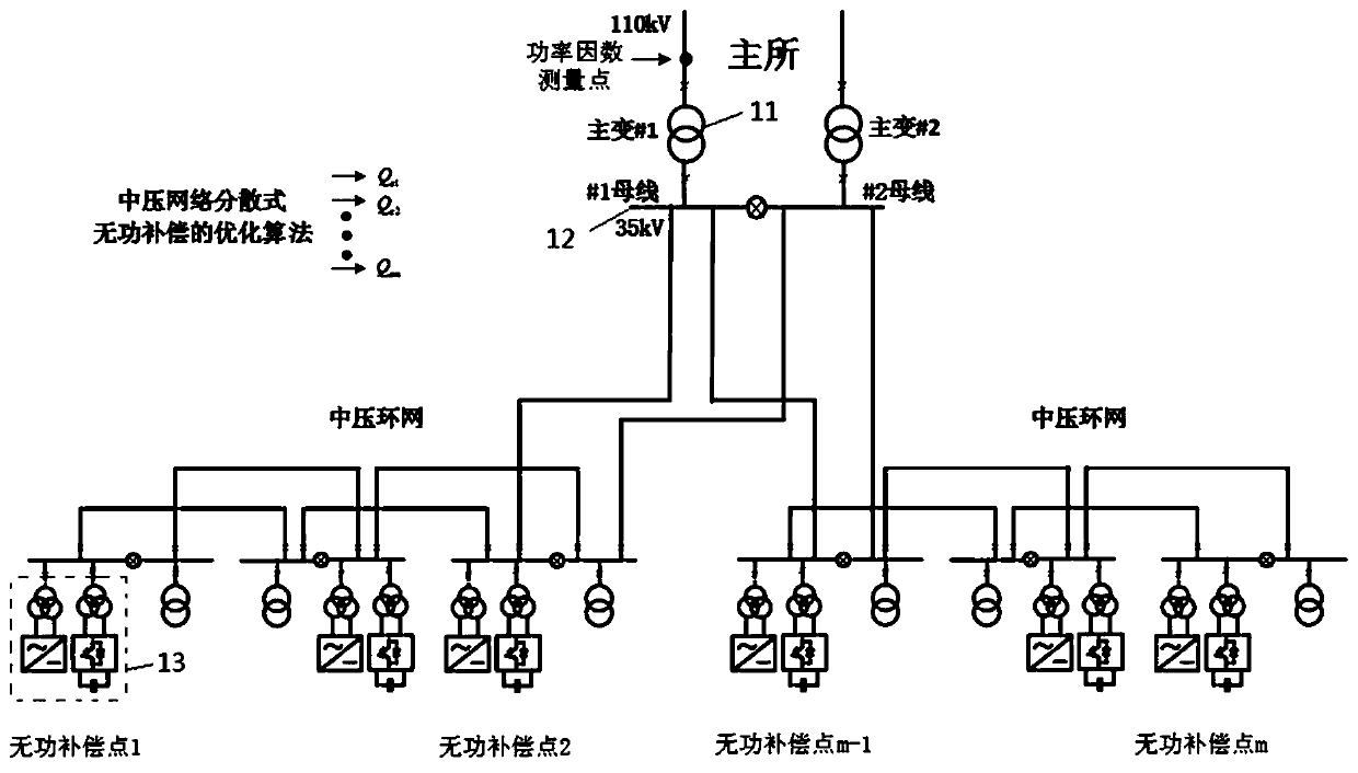
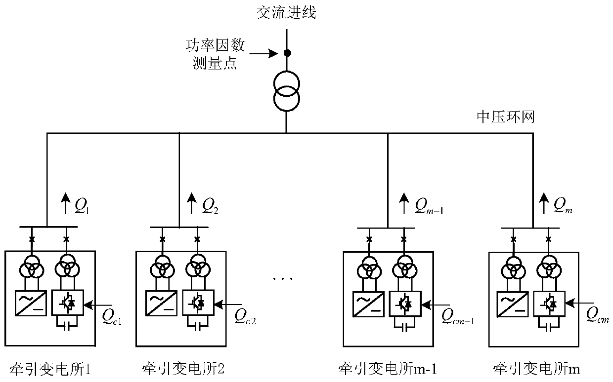
[0021] figure 1 It shows an exemplary system architecture to which the method for reactive power compensation of a medium voltage network according to the embodiment of the present application can be applied.

[0022] Such as figure 1 As shown, the system architecture may include a main substation, and two main transformers 11 may be installed in the main substation. Under normal circumstances, they operate in parallel. The main transformers 11 transmit electric energy to the medium-voltage grid through the bus 12 . The main substation can respectively supply the traction substation 13 and the step-down substation after reducing the voltage of the high-voltage electric energy of the urban power grid. For example, 110KV (or 220KV) electric energy can be stepped down to a voltage level of 35KV or 10KV. The main substation, the traction substation and the step-down substation are connected by cables. The voltage level of the medium voltage network mentioned in this embodiment ...


PUM


Abstract

The invention provides a reactive compensation method and device for a medium-voltage network and a computer readable storage medium. The urban rail transit medium-voltage network comprises a plurality of traction substations which are provided with medium-voltage energy feedback devices and serve as compensation nodes, the medium-voltage energy feedback devices are used for performing distributedreactive power compensation on the urban rail transit medium-voltage network, the optimized reactive compensation amount corresponding to each compensation node is determined based on a particle swarm algorithm; and the medium-voltage energy feedback devices of the compensation nodes are controlled to perform reactive compensation according to the corresponding optimized reactive compensation amount. According to the invention, reactive compensation can be performed by utilizing the existing medium-voltage energy feedback device in the traction substation, and a power grid does not need to betransformed on a large scale, so that the transformation cost is saved. Moreover, the method provided by the invention is based on the particle swarm optimization, can determine the better reactive compensation scheme, and enables a reactive compensation result to be more reasonable.

Description

technical field [0001] The present disclosure relates to reactive power compensation technology, and in particular to a reactive power compensation method, device and computer-readable storage medium for a medium-voltage network. Background technique [0002] The electricity load of urban rail transit system is mainly composed of vehicle traction load and power lighting load. During the nighttime outage of the urban rail transit system, only a small amount of emergency power lighting load, maintenance power load and other loads are put into use, which makes the active power and inductive reactive power generated by the urban rail transit system very small, while the urban rail transit system The generated capacitive reactive power is basically unchanged. In this situation, the urban rail transit system is in the state of capacitive reactive power transfer, resulting in the power factor of the urban rail transit system being as low as below 0.5. If the power factor is too l...

Claims


Application Information

Patent Timeline
Patent Type & Authority Applications(China)
IPC IPC(8): H02J3/18
CPCH02J3/18Y02E40/30
Inventor 陈杰刘志刚吴波田耕耘孟玲敏牟富强张钢邱瑞昌漆良波吕海臣魏路路亮杜军孙星亮刘祥鹏
Owner BEIJING QIANSIYU ELECTRIC
Features
  • R&D
  • Intellectual Property
  • Life Sciences
  • Materials
  • Tech Scout
  • Unparalleled Data Quality
  • Higher Quality Content
  • 60% Fewer Hallucinations
Learn More