Robot power chassis

A power chassis and robot technology, applied in the direction of motor vehicles, power devices, electric power devices, etc., can solve the problems of inconvenient fixed installation and limit adjustment of the main part of the robot, general heat dissipation, poor shock absorption effect, etc., and achieve good elasticity , slow down the vibration, enhance the effect of grip

Inactive Publication Date: 2019-12-03
NANJING HANXIYUE AUTOMATION TECH CO LTD
View PDF7 Cites 8 Cited by
  • Summary
  • Abstract
  • Description
  • Claims
  • Application Information

AI Technical Summary

Problems solved by technology

[0002] With the continuous development of society, people's living standards are rapidly improving, and at the same time as development, science and technology are also making progress. In order to reduce people's work and life burdens, robots that replace people's labor have appeared. Robot power chassis is a kind of The bottom of the robot is used to drive the chassis. Its main function is to have mobility and carrying capacity. It is commonly used in various robots and has a good use effect. The existing robot power plate is not suitable for Moving and running on various terrains, the structure is simple, the function is single, the shock absorption effect is poor, and the heat dissipation is average. During the working process of the robot, many obstacles will be encountered, and the device cannot turn freely, resulting in collisions. damage, and it is not convenient for fixed installation and limit adjustment with the main part of the robot. Here, a robot power chassis is designed to solve the above problems

Method used


Image

  • Robot power chassis
  • Robot power chassis
  • Robot power chassis

Examples


Embodiment 1

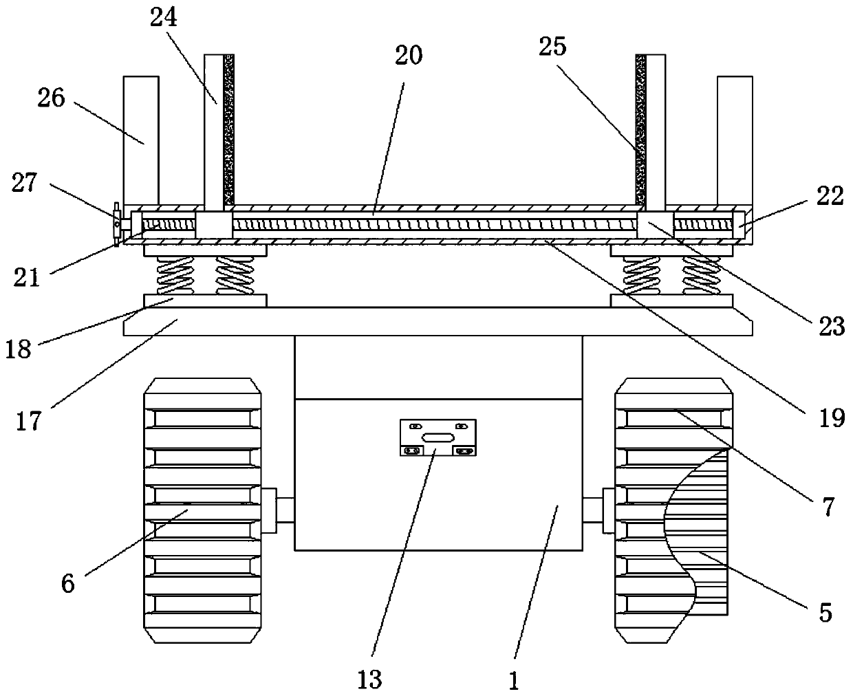
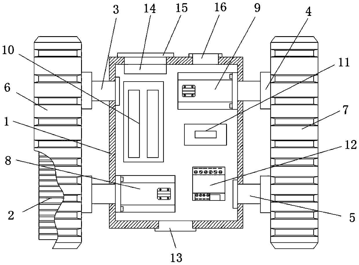
[0035] See Figure 1-4 This embodiment provides a robot power chassis, including a chassis 1, a front end of the chassis 1 is rotatably connected to a right driving wheel 2, and the inside of the chassis 1 is fixedly connected to the position of the right driving wheel 2 The first motor 8, the output end of the first motor 8 is fixedly connected to the right driving wheel 2, the rear end of one side of the chassis 1 is rotatably connected to the right driven wheel 3, and the front end of the other side of the chassis 1 The left driven wheel 5 is rotatably connected, the rear end of the other side of the chassis 1 is rotatably connected to the left driving wheel 4, and the inside of the chassis 1 is fixedly connected to the second motor 9 at the position corresponding to the left driving wheel 4. The output end of the second motor 9 is fixedly connected with the left driving wheel 4, the inside of the chassis 1 corresponding to the rear end of the first motor 8 is fixedly connect...

Embodiment 2

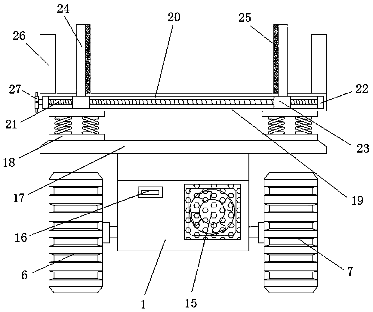
[0039] See Figure 1-7 , A further improvement is made on the basis of embodiment 1: the lower surface of the sliding plate 24 is fixedly connected with a T-shaped slider 29, and the mounting seat 19 is provided with a T-shaped slider that matches the T-shaped slider 29. The sliding connection of the T-shaped sliding block 29 and the T-shaped sliding groove 28 facilitates the sliding of the sliding plate 24 to be smoother, and can effectively prevent the sliding plate 24 from jamming or tilting. A rotating seat 22 is connected to the outer surface wall of one end of the rod 21 corresponding to the inner wall of the sliding groove 20, and the rotating seat 22 is fixedly connected to the inner wall of the sliding groove 20, which facilitates the rotation of the screw 21 and makes the screw 21 The rotation is more smooth, the upper surface of the mounting seat 19 corresponds to the other side of the sliding plate 24, and two baffles 26 are fixedly connected, and the positions of t...


PUM


Abstract

The invention discloses a robot power chassis. The robot power chassis comprises a chassis, wherein a right driving wheel is rotationally connected to the front end of one side of the chassis, and a first motor is fixedly connected to the position, corresponding to the right driving wheel, inside the chassis; the output end of the first motor is fixedly connected with the right driving wheel, anda right driven wheel is rotationally connected to the rear end of one side of the chassis; a left driven wheel is rotationally connected to the front end of the other side of the chassis, a left driving wheel is rotationally connected to the rear end of the other side of the chassis, and a second motor is fixedly connected to the position, corresponding to the left driving wheel, inside the chassis; and the output end of the second motor is fixedly connected with the left driving wheel, and a storage battery is fixedly connected to the rear end, corresponding to the first motor, of the chassis. The power chassis is suitable for moving and running on various terrains, the structure is simple, the damping effect is good, the heat dissipation performance is good, obstacles can be freely turned in the working process of the robot, and therefore collision can be avoided; and meanwhile, fixed installation and limiting adjustment of the power chassis with a robot main body part is convenientto achieve.

Description

Technical field [0001] The present invention relates to the related technical field of power chassis, in particular to a robot power chassis. Background technique [0002] With the continuous development of society, people’s living standards are rapidly improving, and while developing, science and technology are also constantly improving. In order to reduce people’s work and life burdens, robots have emerged to replace people’s labor. Robot powered chassis is a kind of The chassis used to drive the bottom of the robot, its main function is to have mobility and carrying capacity, and it is commonly found in all kinds of robots, and has a good use effect. The existing robot power plate is not suitable for It can move and run on a variety of terrains. The structure is simple, the function is single, the damping effect is poor, and the heat dissipation is average. During the robot's work, many obstacles will be encountered, and the device cannot be turned freely, which will cause col...

Claims


Application Information

Patent Timeline
Patent Type & Authority Applications(China)
IPC IPC(8): B60K1/02B62D55/02B25J5/00B60K11/06B60G13/00
CPCB25J5/005B60G13/003B60K1/02B60K11/06B62D55/02
Inventor 李欣然王远辉严仁
Owner NANJING HANXIYUE AUTOMATION TECH CO LTD
Why Eureka
Try Eureka