Uniform-load thrust bearing
A thrust bearing and thrust technology, applied in the field of thrust bearings, can solve problems such as complex bearing structure, uneven force on pads, reduced equipment reliability and maintainability, etc.
- Summary
- Abstract
- Description
- Claims
- Application Information
AI Technical Summary
Problems solved by technology
Method used
Image

Examples
Embodiment 1
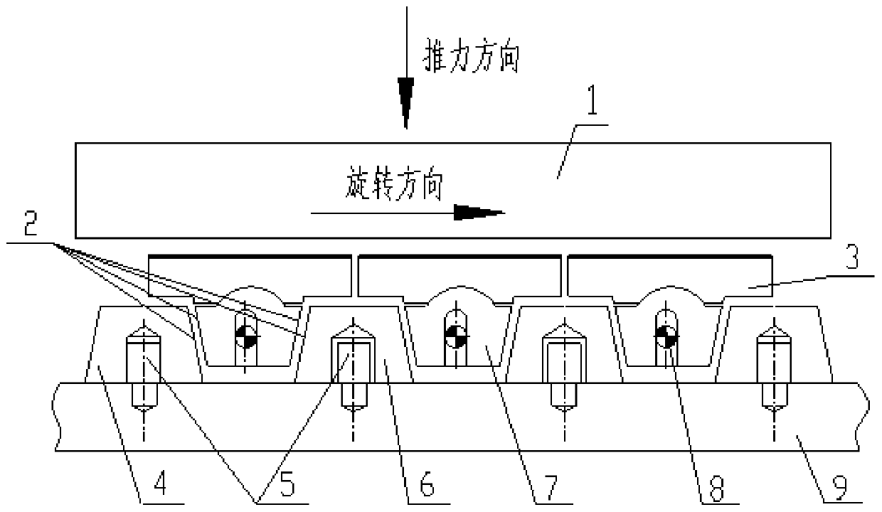
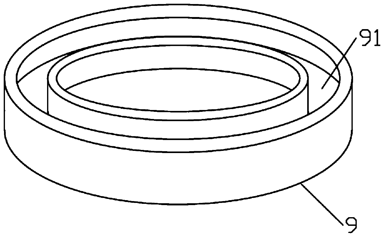
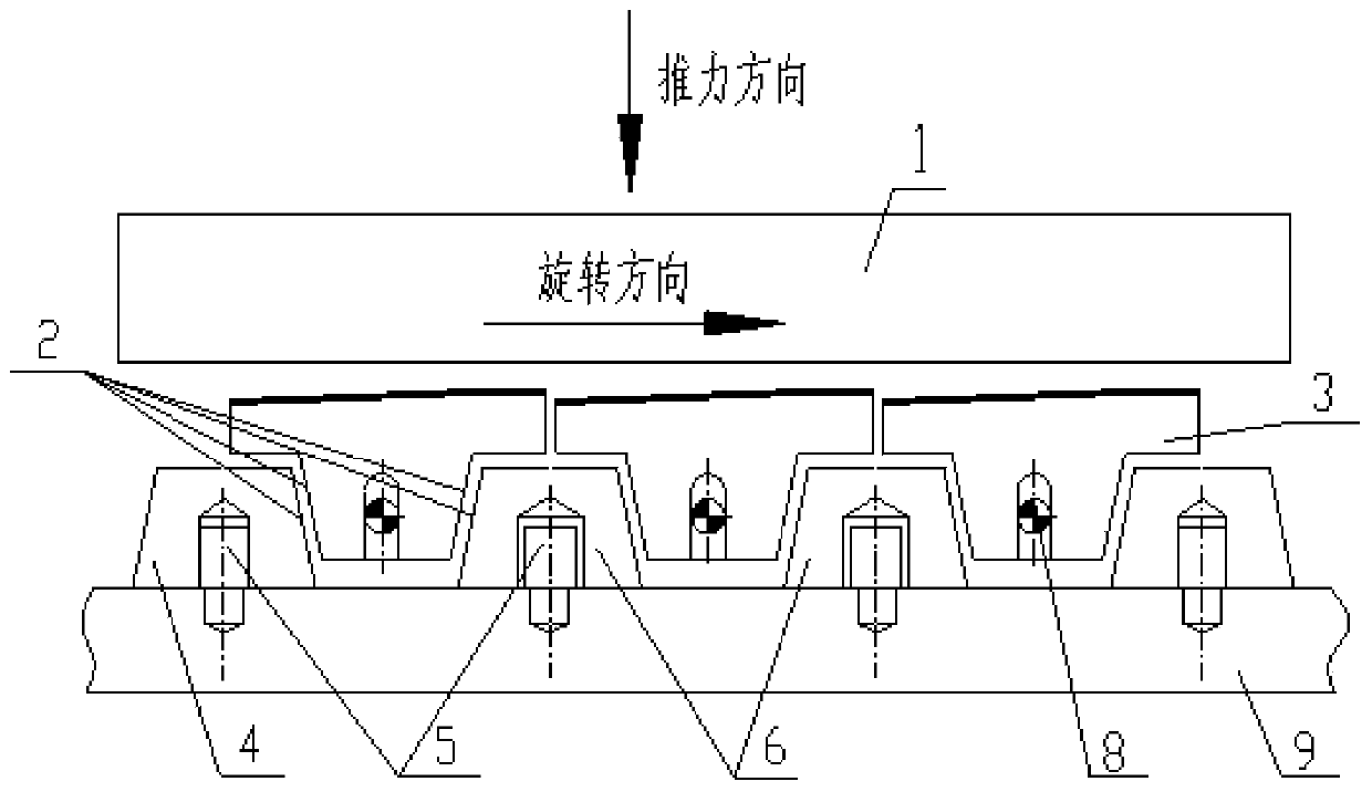
[0019] Such as figure 1 , figure 2 As shown, in this embodiment, a load-sharing thrust bearing includes an annular thrust base ring 9, an annular groove 91 arranged on the thrust base ring 9 and coaxial with the thrust base ring 9, and several annular grooves 91 The load equalizing block inside, several support blocks 7 arranged in the annular groove 91 and distributed at intervals with the load equalizing block and connected by wedge surface 2 transmission, the said load equalizing block includes at least one static joint fixedly connected with the thrust base ring 9 The load equalizing block 4 and several dynamic load balancing blocks 6 are slidably arranged in the annular groove 91 , the wedge surfaces 2 on the support block 7 are facing oppositely, and the support block 7 is connected with the thrust pad 3 .
[0020] In this embodiment, the thrust pad 3 bears the axial thrust from the thrust disc 1 , if the gap distribution between the thrust disc 1 and the thrust pad 3 ...
Embodiment 2
[0024] On the basis of the above embodiments, in this embodiment, the support block 7 is provided with a long hole parallel to the axis of the thrust base ring 9, and the annular groove 91 is provided with a The support block limit pin 8 and the support block 7 are slidably connected with the thrust base ring 9 along the axial direction of the thrust base ring 9 through the cooperation of the support block limit pin 8 and the elongated hole.
[0025] Utilize the cooperation of the elongated hole and the support block stop pin 8, the support block 7 can slide in the annular groove 91 along the axial direction of the thrust base ring 9, so that the outer diameter of the elongated hole is the same as that of the support block stop pin 8 The movement of the support block 7 along the circumferential direction of the annular groove 91 can be restricted by the support block limit pin 8, which is beneficial to improve the control accuracy and stability.
[0026] In this embodiment, se...
Embodiment 3
[0029] On the basis of the above embodiments, in this embodiment, the thrust pad 3 is rotatably installed on the support block 7, so that when the thrust pad 3 is subjected to uneven thrust, the thrust pad 3 can be rotated The angle or gap between the thrust pad 3 and the thrust disc 1 is adaptively adjusted, so that the thrust pad 3 can be evenly stressed.
[0030] In this embodiment, the thrust pad 3 and the support block 7 are connected through a spherical surface, and the thrust pad 3 can be adjusted from multiple angles and directions relative to the support block 7 by using the spherical connection, which can increase the flexibility of the thrust pad 3 . Utilizing the spherical surface can disperse the pressure transmitted from the thrust pad 3 to the support block 7, which is beneficial to reduce the wear between the thrust pad 3 and the support block 7, and prevent the connection structure between the thrust pad 3 and the support block 7 from being compressed. damage...
PUM
 Abstract
Description
Claims
Application Information
 - R&D
- Intellectual Property
- Life Sciences
- Materials
- Tech Scout
- Unparalleled Data Quality
- Higher Quality Content
- 60% Fewer Hallucinations
Browse by: Latest US Patents, China's latest patents, Technical Efficacy Thesaurus, Application Domain, Technology Topic, Popular Technical Reports.
© 2025 PatSnap. All rights reserved.Legal|Privacy policy|Modern Slavery Act Transparency Statement|Sitemap|About US| Contact US: help@patsnap.com