Catalytic oil-free compression system

A compression system and compressor technology, applied in chemical instruments and methods, separation methods, liquid variable capacity machines, etc., can solve problems such as catalyst overload failure, oil running, and limited catalyst oil removal efficiency.

Pending Publication Date: 2022-05-06
NINGBO BAOSI ENERGY EQUIP
View PDF0 Cites 0 Cited by
  • Summary
  • Abstract
  • Description
  • Claims
  • Application Information

AI Technical Summary

Problems solved by technology

[0003] The oil removal efficiency of the catalyst is limited. If the seal of the compressor fails to cause oil leakage, or the application environment of the catalytic oil-free compression system has a high concentration of oil mist and oil vapor, a large amount of oil impurities (oil droplets) will , oil mist, oil vapor, etc.) will enter the oil-free catalytic machine with the compressed gas. Once the oil impurities exceed the maximum load capacity of the catalyst, the catalyst will not be able to fully handle the maximum oil removal efficiency,

Method used


Image

  • Catalytic oil-free compression system
  • Catalytic oil-free compression system
  • Catalytic oil-free compression system

Examples


Embodiment 1

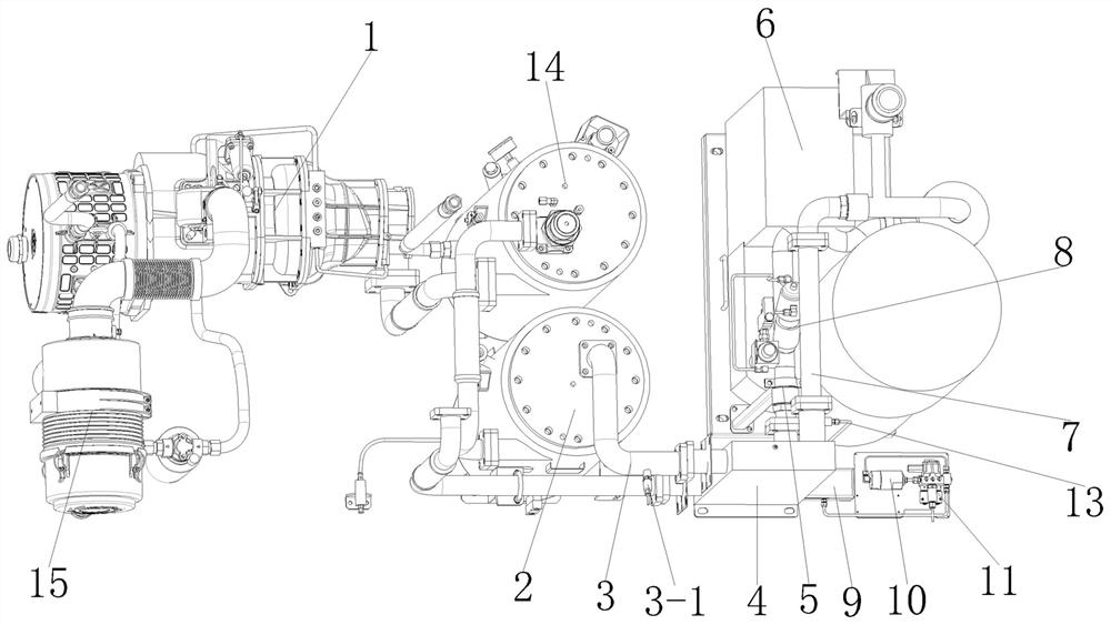
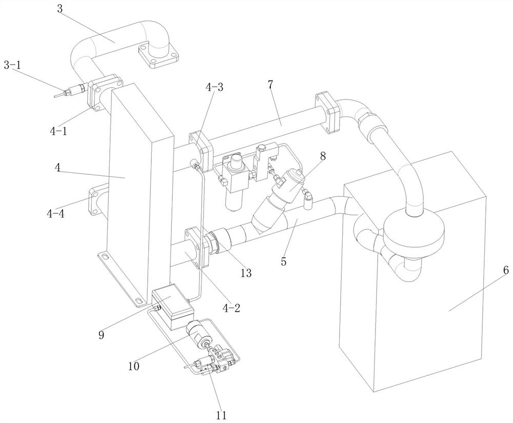
[0023] Such as figure 1 and figure 2 As shown in , the catalytic oil-free compression system of the present invention includes a compressor 1, an oil-gas separation device 14, a water-gas separation device 2, an oil-free catalytic engine 6, a first detection unit 3, a second detection unit 11, and a heat exchange device 4 , data processing unit, air pressure detection unit, humidity detection unit. The compressor 1 can be an oil-lubricated compressor, or other dry compressors, and can be various types of compressors such as high pressure, medium pressure, and low pressure. The air inlet and exhaust port of the oil-free catalytic machine 6 are respectively provided with a catalytic equipment intake pipe 5 and a catalytic equipment exhaust pipe 7 , and an angle seat valve 8 is also arranged on the catalytic equipment intake pipe 5 . As a delayed exhaust device, the heat exchange device 4 is provided with a cold air passage and a hot air passage. The cold air passage and the h...

Embodiment 2

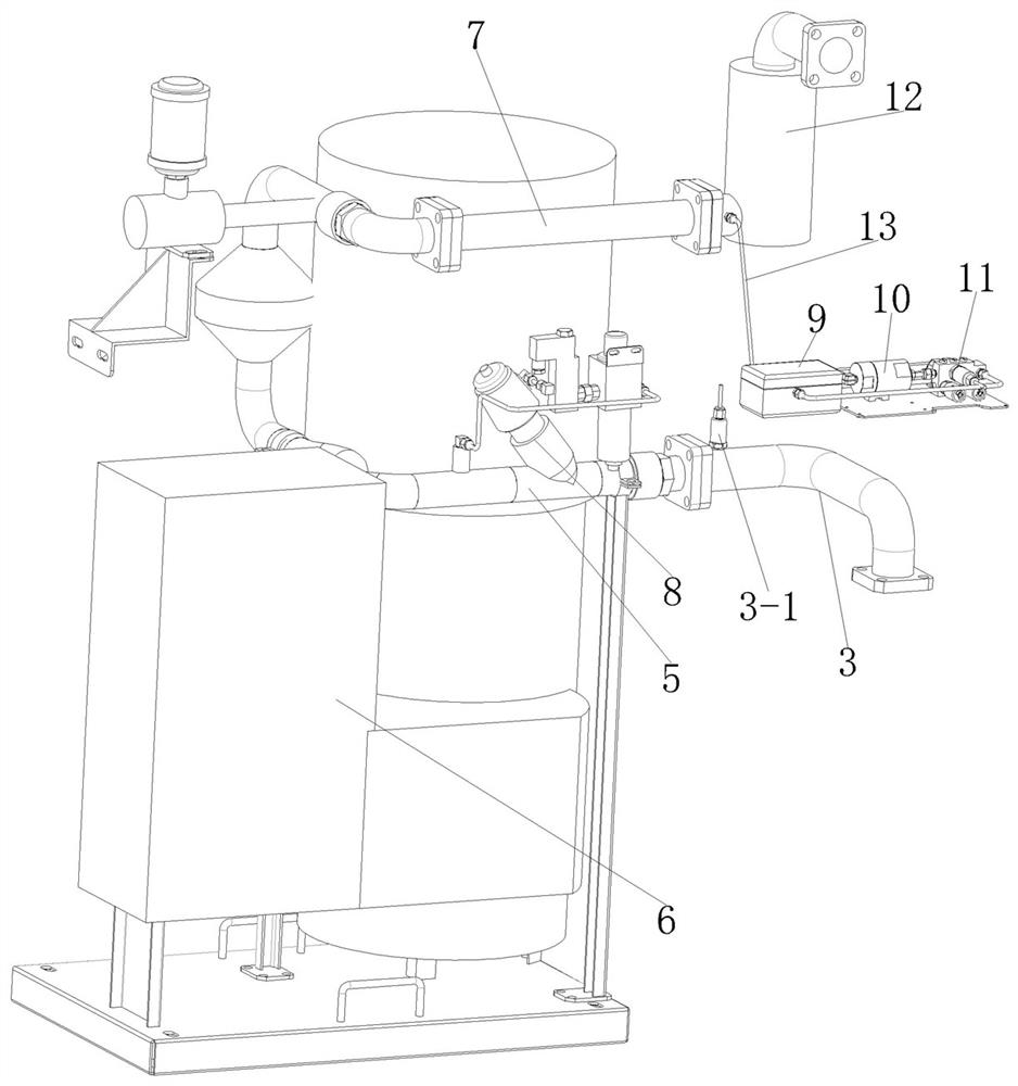
[0029] Such as image 3 As shown in , the difference between the catalytic oil-free compression system of the present embodiment and the embodiment 1 is that the heat exchange device 4 is not provided in the present embodiment, but a delay exhaust pipe 12 is provided, and the delay exhaust pipe 12 serves as The delay exhaust device is provided with a spiral air channel or a multi-turn U-shaped air channel inside. The exhaust port of the water-gas separation device 2 is connected with the intake pipe 5 of the catalytic device, and the delayed exhaust pipe 12 is connected with the exhaust port of the catalytic device. The gas pipe 7 is connected, and the compressed gas discharged from the compressor 1 enters the oil-free catalytic machine 6 for catalytic oil removal after oil-gas separation and water-gas separation, and then is discharged through the delayed exhaust pipe 12 . The first detection unit 3 is arranged on the intake pipe 5 of the catalytic device, and detects the oil...


PUM


Abstract

The invention provides a catalytic oil-free compression system which comprises a compressor, an oil-free catalytic engine, a first detection unit, a second detection unit and a data processing unit, the exhaust end of the compressor is connected with the gas inlet end of the oil-free catalytic engine, and the oil-free catalytic engine is used for conducting catalytic oil removal on compressed gas exhausted by the compressor; the first detection unit is arranged at the gas inlet end of the oil-free catalytic engine and detects the oil content of compressed gas before the compressed gas enters the oil-free catalytic engine in real time, and the second detection unit is arranged at the gas outlet end of the oil-free catalytic engine and detects the oil content of the compressed gas subjected to catalytic oil removal through the oil-free catalytic engine in real time. The data processing unit is electrically connected with the first detection unit and the second detection unit, and the data processing unit compares the detection result of the first detection unit with the detection result of the second detection unit in real time. According to the invention, a user can grasp the oil removal efficiency of the catalyst in real time, and confirm that the type and dosage of the catalyst meet the gas demand of the industry.

Description

technical field [0001] The invention relates to the technical field of compressed gas purification, in particular to a catalytic oil-free compression system. Background technique [0002] In the current hot field of hydrogen energy, hydrogen storage, hydrogen transportation, hydrogenation and other links need to compress hydrogen. If the compressed hydrogen contains oily pollutants, it is extremely detrimental to hydrogen fuel cells. The existing technology usually An oil-free catalytic machine is installed at the exhaust end of the compressor to remove oil pollutants in the compressed gas. The oil-free catalytic machine adopts catalytic oxidation technology. The core material is a catalyst. The compressed air is heated to a certain temperature by a heater. The catalyst Under this temperature environment, the hydrocarbons (including oil molecules) in the compressed gas react chemically with oxygen, and finally generate clean carbon dioxide and water, completely solving the p...

Claims


Application Information

Patent Timeline
IPC IPC(8): F04B49/06B01D53/86
CPCF04B49/06B01D53/86F04B2205/50
Inventor 张超萍张炯焱王泉超
Owner NINGBO BAOSI ENERGY EQUIP
Why Eureka
Try Eureka