Lifting device for painting spraying of front shaft of automobile forge piece

A lifting device, forging technology, applied in the direction of injection device, etc., can solve problems such as low work efficiency, and achieve the effect of improving work efficiency, reasonable structure design and saving manpower

Inactive Publication Date: 2019-12-06
ANHUI HEFEI AUTO FORGING
View PDF8 Cites 1 Cited by
  • Summary
  • Abstract
  • Description
  • Claims
  • Application Information

AI Technical Summary

Problems solved by technology

[0007] The purpose of the present invention is to overcome the deficiencies of the prior art and to meet the actual needs, to provide a lifting device for painting and spraying the front axle of automobile forgings, so as to solve the problem of low work efficiency when painting existing automobile forgings

Method used


Image

  • Lifting device for painting spraying of front shaft of automobile forge piece
  • Lifting device for painting spraying of front shaft of automobile forge piece
  • Lifting device for painting spraying of front shaft of automobile forge piece

Examples


Embodiment 1

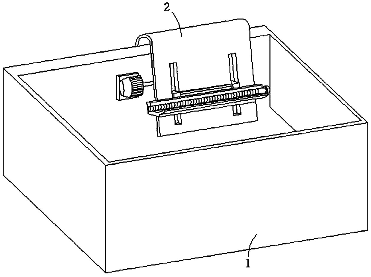
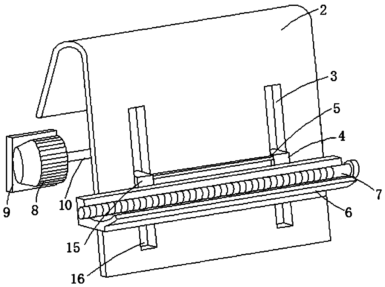
[0033] Such as Figure 1-4 As shown, in this embodiment, a lifting device for painting and spraying the front axle of automobile forgings is proposed, which includes a spraying support frame 1 and a cooling assembly. The cooling assembly includes a support frame 2 and a drive motor 8. The first moving through hole 3 and the second moving through hole 16, and the first sliding block 4 and the second sliding block 15 are slidingly arranged in the first moving through hole 3 and the second moving through hole 16 respectively, and the first sliding block 4 It is connected with the second sliding block 15 through the connecting rod 5, and the first sliding block 4 and the second sliding block 15 are jointly connected with a placement groove 6, and the forging body 7 is placed on the placement groove 6, and the driving motor 8 is fixedly arranged On the fixed plate 9, and the fixed plate 9 is fixedly arranged in the spraying support frame 1, the driving part of the driving motor 8 i...

Embodiment 2

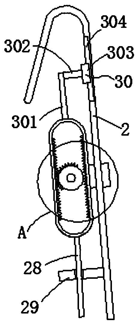
[0038] Such as image 3 As shown, the difference between Embodiment 2 and Embodiment 1 is that in Embodiment 2, a guide assembly 30 is added, and the setting of the guide assembly 30 can be used to guide the movement of the ring gear 12 to ensure that the ring gear 12 Only move on the same trajectory, and the setting of the guide assembly 30 can also cooperate with the combination of the slide bar 28 and the support plate 29 to support the ring gear 12, so that the sliding bar 28 and the support plate 29 can be avoided. The combined force is too large, thereby delaying the service life of the combination of the sliding rod 28 and the support plate 29 .

Embodiment 3

[0040] Such as Figure 5 and Figure 6As shown, the difference between embodiment 3 and embodiments 1 and 2 is that in embodiment 3, a rotating assembly is added, and the setting of the rotating assembly is used to rotate when the forging body 7 moves up and down, and the rotation of the forging body 7 can be Accelerate the contact with the liquid paint, so as to improve the spray effect, specifically, the rotation process is as follows:

[0041] The up and down movement of the placement slot 6 will rotate with the first full gear 17 through the spur rack 14, and the rotation of the first full gear 17 will rotate with the first rotating rod 19, and the rotation of the first rotating rod 19 will pass through the conveyor belt 20. And the second rotating rod 21 rotates with the second full gear 22, the rotation of the second full gear 22 will bring the rotation of the third full gear 24 and the fourth full gear 26, so that the third full gear 24 and the fourth full gear are pla...


PUM


Abstract

The invention relates to a lifting device for painting spraying of a front shaft of an automobile forge piece. The lifting device aims at solving the problem that during painting of an existing automobile forge piece, the work efficiency is low. The lifting device comprises a spraying supporting frame and a cooling assembly. The cooling assembly comprises a supporting frame and a drive motor. Thesupporting frame is provided with a first moving through hole which is through and a second moving through hole which is through, and a first sliding block and a second sliding block are arranged in the first moving through hole and the second moving through hole correspondingly in a sliding manner. The lifting device is reasonable in structural design, in the spraying process of the forge piece,the effect of saving time and labor can be conveniently achieved, in addition, the fast painting effect can be achieved, in the practical work process, painting of the forge piece can be completed within shorter time, and therefore the work efficiency is improved.

Description

technical field [0001] The invention relates to the technical field of automobile forging equipment, in particular to a lifting device for painting and spraying the front axle of automobile forgings. Background technique [0002] Forging is a machining process. A forging is an object in which a metal is pressured to form a required shape or a suitable compression force through plastic deformation. This force is typically achieved through the use of a hammer or pressure. The forging process creates a refined grain structure and improves the physical properties of the metal. In the actual use of components, a correct design can make the particle flow in the direction of the main pressure. Forgings need to be consistent from piece to piece, free of any porosity, inclusions, or other blemishes. Components produced by this method have a high ratio of strength to weight. The advantages of forgings are stretchable length; shrinkable length, stretchable cross section; changeabl...

Claims


Application Information

Patent Timeline
Patent Type & Authority Applications(China)
IPC IPC(8): B05B13/02
CPCB05B13/0221B05B13/0235
Inventor 朱腾鲁传锐秦学枫周昌根
Owner ANHUI HEFEI AUTO FORGING
Why Eureka
Try Eureka