Lamination machine

A technology of gluing machine and geared motor, which is applied in the direction of coating, device for coating liquid on the surface, etc., can solve the problems of complex structure, high maintenance cost and complex structure of gluing equipment.

Pending Publication Date: 2019-12-06
GUANGBO GRP
View PDF1 Cites 2 Cited by
  • Summary
  • Abstract
  • Description
  • Claims
  • Application Information

AI Technical Summary

Problems solved by technology

[0003] In the processing process of the gummed paper in the prior art, there must be a process of gluing one end of the gummed paper; in the prior art, the single-sided gluing process generally adopts that the glue is applied to the gummed paper manually, so The accuracy of the brushing method is low, and it is easy to have a lot of glue on one part of the glued paper and less glue on the other; machine, but the structure of the single-sided gluing machine in the prior art is relatively complicated, and a large number of rotating devices are often added on the upper end of the roller for gluing the paper, which makes the structure of the whole gluing equipment complicated and inconvenient to maintain. High cost situation
[0004] For example: Patent No.: 200910106049.4 describes a gluing machine with a monitoring and protection device. This gluing machine is a relatively common single-sided gluing machine. The gluing machine contains a large number of transmission mechanisms for driving the rotation of the drum. When the machine needs to maintain and repair the transmission mechanism, it is difficult to maintain because the transmission mechanisms are closely arranged.

Method used


Image

  • Lamination machine
  • Lamination machine
  • Lamination machine

Examples


Embodiment 1

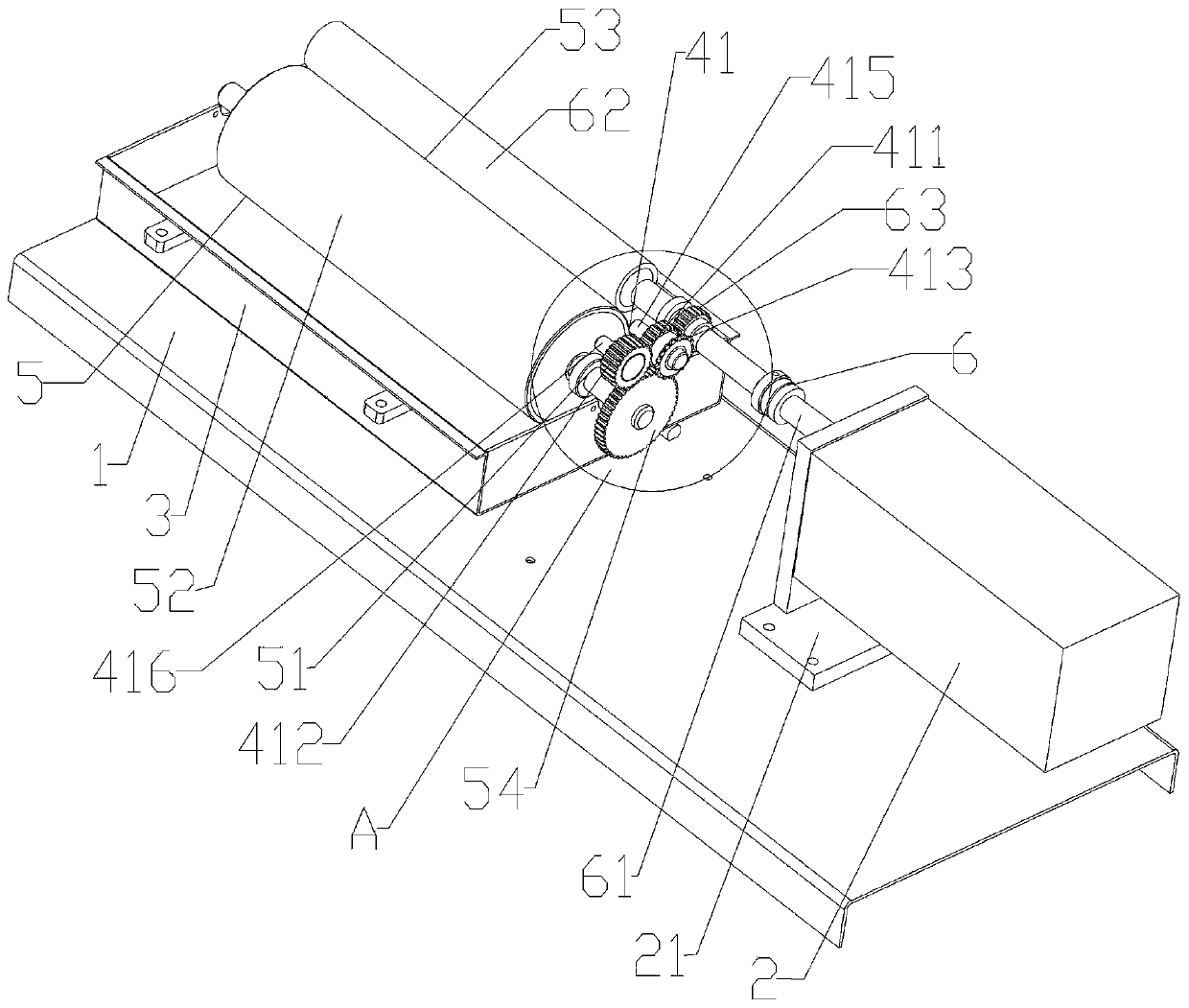
[0025] Embodiment 1: see figure 2 In this technical solution, one end of the driving shaft is fixedly connected to the power output end of the geared motor, and when the rotating shaft of the geared motor rotates in the circumferential direction, it will drive the driving shaft to rotate in the circumferential direction, and the circumferential rotation of the driving shaft will drive the gear box. The first gear rotates in the circumferential direction, and the circumferential rotation of the first gear will drive the third gear meshed with it to rotate in the circumferential direction, and the circumferential rotation of the third gear will be driven by the fourth gear meshed with the third gear. Circumferential rotation, and the circumferential rotation of the fourth gear is driven by the second gear meshed with the fourth gear to perform circumferential rotation, and the circumferential rotation of the second gear is driven by the driven shaft connected to the outer wall o...


PUM


Abstract

The invention discloses a lamination machine which comprises a base of the lamination machine, wherein a speed reduction motor and a storage groove used for storage of glue are disposed on the base; agearbox used for storing a gear set is also disposed on the base; a first rolling mechanism is in rotatable connection to the upper end face of the storage groove; a second rolling mechanism which islocated above the first rolling mechanism is in rotatable connection to the outer side wall of the gearbox; the first rolling mechanism is in transmission connection to the second rolling mechanism by the gear set; a fixation mechanism which can adhere a to-be-laminated product with the outer side wall of the second rolling mechanism is disposed above the second rolling mechanism; and the end, remote from the first rolling mechanism, of the second rolling mechanism passes through the gearbox and is then fixedly connected to a power output end of the speed reduction motor.

Description

technical field [0001] The invention relates to the technical field of gluing machines, in particular to a gluing machine. Background technique [0002] Laminating machine is also called plastic sealing machine. Its gluing treatment is polyester film coated with hot melt adhesive. Through the processing of gluing machine, the sealed items are glued into the plastic film. Since the processing process is carried out under certain pressure and high temperature, and high-quality polyester film and hot-melt adhesive with good transparency are used, it can not only ensure that the plastic-sealed items are not damaged at room temperature, but also increase the intuitive effect. [0003] In the processing process of the gummed paper in the prior art, there must be a process of gluing one end of the gummed paper; in the prior art, the single-sided gluing process generally adopts that the glue is applied to the gummed paper manually, so The accuracy of the brushing method is low, an...

Claims


Application Information

Patent Timeline
Patent Type & Authority Applications(China)
IPC IPC(8): B05C1/08B05C13/02
CPCB05C1/0821B05C1/083B05C13/02
Inventor 徐腾
Owner GUANGBO GRP
Why Eureka
Try Eureka