High-efficiency pretreatment device for motor shell inner side surface rough machining

A technology for the inner surface of the motor shell, which is applied in the field of high-efficiency rough machining and pretreatment equipment for the inner surface of the motor shell. The effect of positioning clamping

Active Publication Date: 2019-12-06
马鞍山常裕机械设备股份有限公司
View PDF12 Cites 5 Cited by
  • Summary
  • Abstract
  • Description
  • Claims
  • Application Information

AI Technical Summary

Problems solved by technology

[0005] Aiming at the deficiencies of the prior art, the present invention provides a high-efficiency rough machining pretreatment equipment for the inner surface of the motor casing, which can conveniently position and clamp the motor casing, improves the processing efficiency of the motor casing, and can facilitate polishing The debris generated during cleaning can be cleaned, and the debris can be easily collected. It solves the problem that when the motor shell is pretreated, the motor shell needs to be fixed and clamped first, and when it is fixed, it cannot be used for different sizes and models. The motor shell is fixed and clamped, and the staff needs to manually adjust the machining position of the motor shell, which is too cumbersome and inconvenient, and will affect the processing efficiency of the motor shell

Method used


Image

  • High-efficiency pretreatment device for motor shell inner side surface rough machining
  • High-efficiency pretreatment device for motor shell inner side surface rough machining
  • High-efficiency pretreatment device for motor shell inner side surface rough machining

Examples


Embodiment Construction

[0023] The following will clearly and completely describe the technical solutions in the embodiments of the present invention with reference to the accompanying drawings in the embodiments of the present invention. Obviously, the described embodiments are only some, not all, embodiments of the present invention. Based on the embodiments of the present invention, all other embodiments obtained by persons of ordinary skill in the art without making creative efforts belong to the protection scope of the present invention.

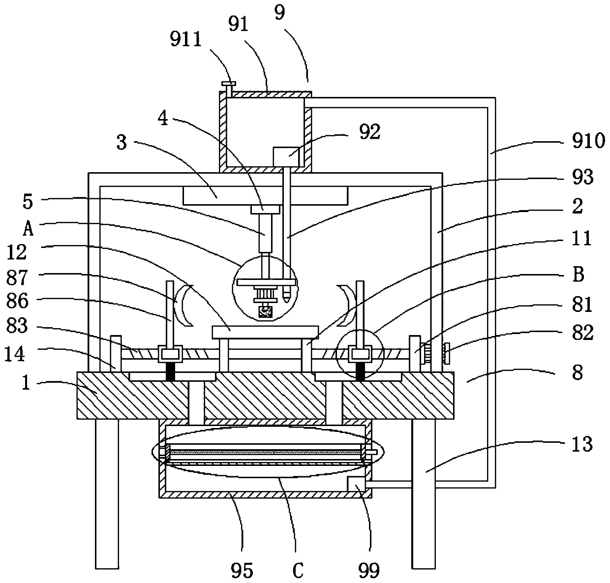
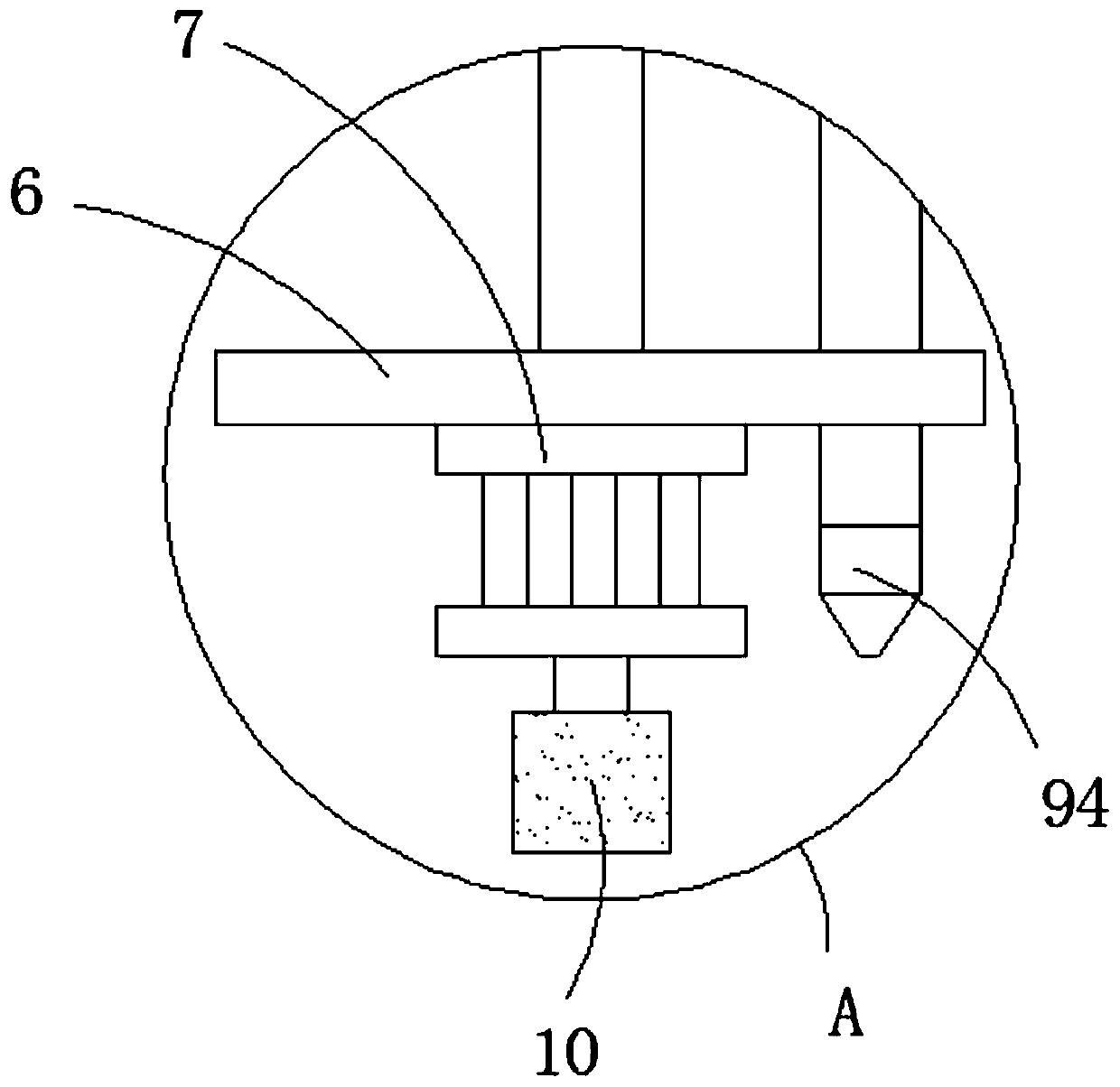
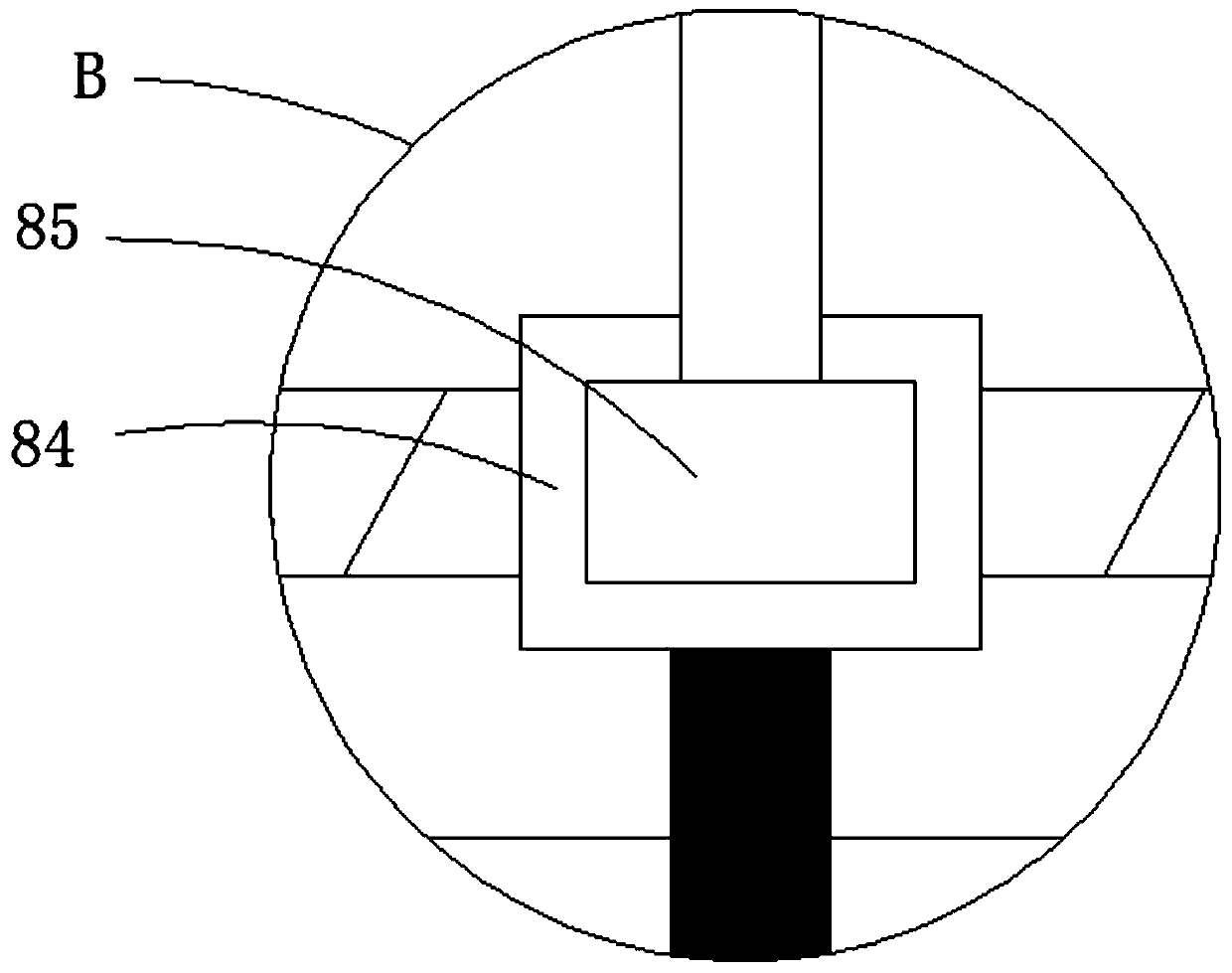
[0024] see Figure 1-4 , a high-efficiency rough machining pretreatment equipment for the inner surface of the motor shell, including a workbench 1, the upper surface of the workbench 1 is fixedly connected with a frame 2, the top inner wall of the frame 2 is fixedly connected with an electric slide rail 3, and the electric slide The bottom of the rail 3 is slidingly connected with the moving block 4, the bottom of the moving block 4 is fixedly connected with ...


PUM


Abstract

The invention relates to the technical field of motor shell machining devices, and discloses a high-efficiency pretreatment device for motor shell inner side surface rough machining. The device comprises a worktable, a machine frame is fixedly connected with the upper surface of the worktable, an electric slide rail is fixedly connected with the inner wall of the top of the machine frame, the bottom of the electric slide rail is slidably connected with a movable block, the bottom of the movable block is fixedly connected with an electric push rod, the bottom of the electric push rod is fixedlyconnected with a support plate, the bottom of the support plate is fixedly connected with a first rotary motor, the output end of the first rotary motor is fixedly connected with a polishing pad, theupper surface of the worktable is fixedly connected with a clamping mechanism, and the top of the machine frame is fixedly connected with a debris cleaning mechanism. According to the high-efficiencypretreatment device for motor shell inner side surface rough machining, a motor shell can be conveniently positioned and clamped, the machining efficiency of the motor shell is improved, meanwhile, debris generated during polishing can be conveniently cleaned, and the debris can be conveniently collected.

Description

technical field [0001] The invention relates to the technical field of motor shell processing equipment, in particular to a high-efficiency rough machining pretreatment equipment for the inner surface of a motor shell. Background technique [0002] After the casting of the motor casing, a series of surface processing is required. In order to ensure the accuracy of the inner wall of the motor casing, the inner surface of the motor casing generally needs to be processed in multiple processes. When the motor casing is processed, the inner wall of the motor casing The surface is relatively rough or there are processing burrs left. For the case where the inner wall of the motor housing is relatively rough, the machining tool wears more seriously during the machining process, which is not conducive to the safe cutting of the machining tool in the machining process. Therefore, it is necessary to rough the motor housing. Pretreatment is carried out before processing to remove impuri...

Claims


Application Information

Patent Timeline
Patent Type & Authority Applications(China)
IPC IPC(8): B24B9/04B24B41/06B24B55/06B24B29/02B24B27/033B03C1/02
CPCB03C1/02B24B9/04B24B27/033B24B29/02B24B41/06B24B55/06
Inventor 蔡发华
Owner 马鞍山常裕机械设备股份有限公司
Why Eureka
Try Eureka