
Cutting device for flush cut of plastic product

A technology for a plastic product and a cutting device, which is applied to the field of cutting devices for flush incisions of plastic products pipes, can solve the problems of processing and uneven incisions of plastic pipes, and achieve the effects of easy processing, maintaining flushness, and strong practicability.

Active Publication Date: 2019-12-06
安徽省宣城市联通塑业有限责任公司
View PDF10 Cites 3 Cited by
  • Summary
  • Abstract
  • Description
  • Claims
  • Application Information

AI Technical Summary

Problems solved by technology

[0004] The object of the present invention is to provide a cutting device for flush cutting of plastic pipes to solve the problem that the plastic pipe cuts are not flush and require subsequent processing

Method used


Image

  • Cutting device for flush cut of plastic product
  • Cutting device for flush cut of plastic product
  • Cutting device for flush cut of plastic product

Examples


Embodiment 1

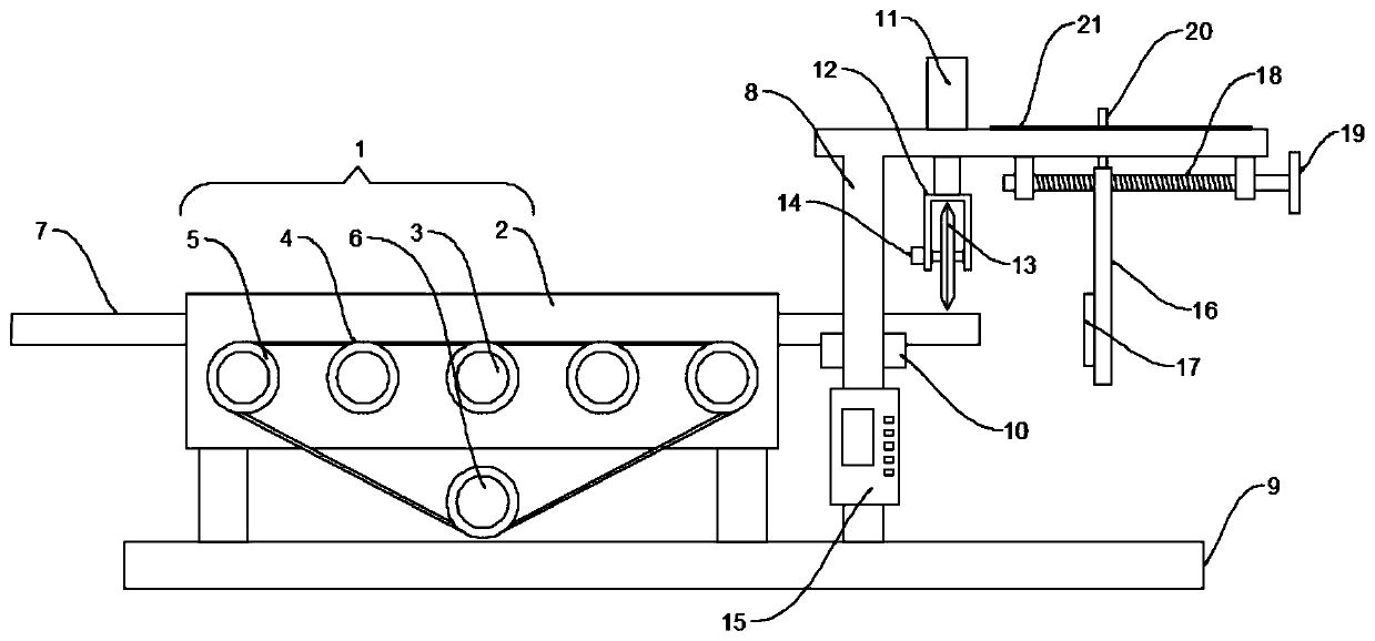
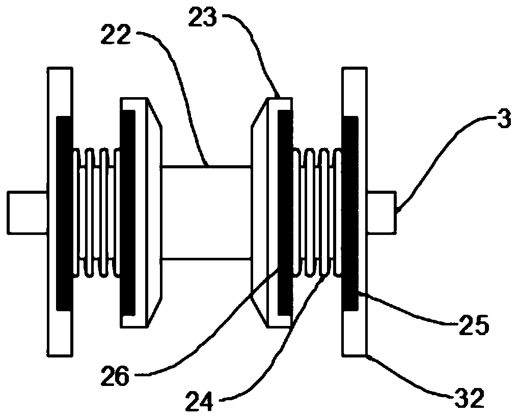
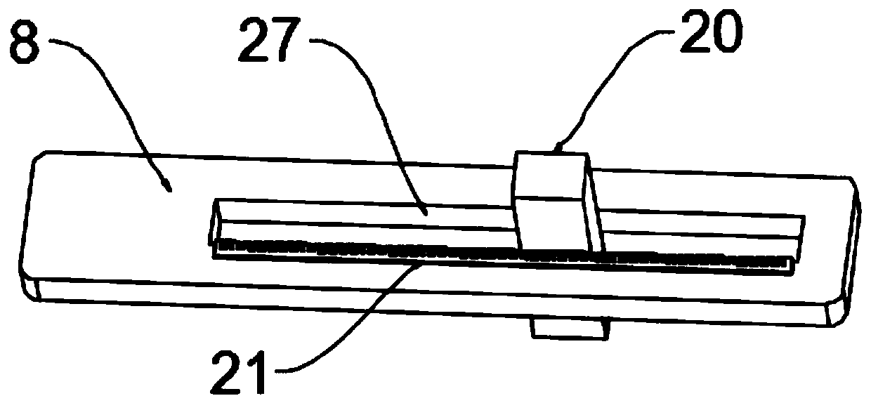
[0024] see Figure 1~3 , in an embodiment of the present invention, a cutting device for a flush cut of a plastic product tube includes a feeding and pushing mechanism 1, a cutting mechanism and a base substrate 9, the feeding and pushing mechanism 1 is arranged on the base substrate 9 and the feeding and pushing mechanism The mechanism 1 includes a conveying frame body 2, a plurality of conveying rod shafts 3 arranged horizontally on the conveying frame body 2 and a push motor 6 arranged on the base substrate 9, each end of the conveying rod shaft 3 and the output end of the push motor 6 Both are provided with a sprocket 5, and a plurality of sprockets 5 are connected by a chain 4 around it, and each delivery rod shaft 3 is also fixed with a fixed sleeve 22, and the fixed sleeve 22 is provided with two slides on it. Clamping disc 23, the diameters of the two clamping discs 23 gradually become smaller from the opposite end to the opposite end, both ends of the fixing sleeve 22...

Embodiment 2

[0028] see Figure 4 The difference between the embodiment of the present invention and embodiment 1 is that: the horizontal rod of the installation rod frame 8 is also provided with a suspension vertical plate 16 at the end of the feeding push mechanism 1, and the suspension vertical plate 16 is provided with a pressure Inductor 17, a control box 15 that electrically controls the lifting cylinder 11 and the push motor 6 is also provided on the wall of the rod frame 8, and the control box 15 is equipped with an electric control system, and the electric control system includes a receiving unit 29. The central processing unit 28 and the output unit 30, the receiving unit 29 is used to electrically connect the pressure sensor 17 and receive the signal transmitted by the pressure sensor 17; the central processing unit 28 is used to generate according to the signal transmitted by the receiving unit 29 The control command is transmitted to the output unit 30, and the output unit 30 ...


PUM


Abstract

The invention discloses a cutting device for flush cut of a plastic product, relates to the technical field of plastic product processing and mainly aims to solve the problem that the cut of a plastictube is not flush and needs follow-up processing. The cutting device comprises a loading pushing mechanism, a cutting mechanism and a base substrate, wherein the loading pushing mechanism is arrangedon the base substrate, and comprises a conveying frame body, a plurality of conveying rod shafts which are horizontally arranged on the conveying frame body and a pushing motor arranged on the base substrate; a fixed sleeve is further fixed on each conveying rod shaft, two clamping discs capable of sliding on the fixed sleeve are arranged on the fixed sleeve in a sleeving mode, the two ends of the fixed sleeve are fixedly equipped with side plates, and the end surfaces, close to the side plates, of the clamping discs are equipped with magnetic plates. The cutting device is simple in mechanism, facilitates pushing guide tubes, guarantees that the plastic tube linearly moves to match with vertical movement of a cutting sheet and tube cut flush degree is relatively high, facilitates follow-up port processing and is relatively high in practicability.

Description

technical field [0001] The invention relates to the technical field of plastic product processing, in particular to a cutting device for flush cutting of plastic product tubes. Background technique [0002] Plastic products are a general term for household and industrial products processed from plastic as the main raw material. Including plastic as raw material for injection molding, blister and other products of all processes. Plastic is a kind of synthetic polymer material with plasticity. It forms three indispensable synthetic materials in daily life together with synthetic rubber and synthetic fiber. Specifically, plastic is a material with natural or synthetic resin as the main component, adding various additives, which can be molded into a certain shape under certain conditions such as temperature and pressure, and maintains the same shape at room temperature. [0003] Plastic product pipes need to be cut to a certain length before use. The current plastic pipe cutti...

Claims


Application Information

Patent Timeline
Patent Type & Authority Applications(China)
IPC IPC(8): B26D1/16B26D5/04B26D5/08B26D7/02B26D7/06B26D7/28
CPCB26D1/16B26D5/04B26D5/086B26D7/02B26D7/0608B26D7/28B26D2007/013
Inventor 柳明观
Owner 安徽省宣城市联通塑业有限责任公司
Learn More