Image stitching system and image stitching method

An image stitching and stitching system technology, applied in the field of image processing, can solve the problems of large depth of field error, inability to stitch, correct shape, etc.

Pending Publication Date: 2019-12-06
JINAN SHENBO INFORMATION TECH
View PDF4 Cites 1 Cited by
  • Summary
  • Abstract
  • Description
  • Claims
  • Application Information

AI Technical Summary

Problems solved by technology

The disadvantage of single-camera rotation stitching is that the distortion is very serious. Because its core principle is to use the images collected by multiple ordinary lenses to stitch together an image collected by a super wide-angle lens, it inherits the shortcomings of the super wide-angle lens. The closer to the edge of the stitched image , there is a perspective transformation with a larger angle, and the greater the error of its depth of field, so when shooting an object with a depth of field, its distortion cannot be corrected to obtain the correct shape in the later stage; due to the existence of parallax, multi-view stitching cannot correctly perform image processing. Registration
Therefore, it is required that the object to be photographed is a plane or the distance from the object to be photographed is much higher than the depth of field change of the object to be photographed. Therefore, this scheme cannot successfully splice images captured by close-up objects with depth of field into ultra-wide-view images.

Method used


Image

  • Image stitching system and image stitching method
  • Image stitching system and image stitching method
  • Image stitching system and image stitching method

Examples


Embodiment Construction

[0037] In order to enable those skilled in the art to better understand the present invention, the technical solutions of the present invention will be further described below in conjunction with the accompanying drawings.

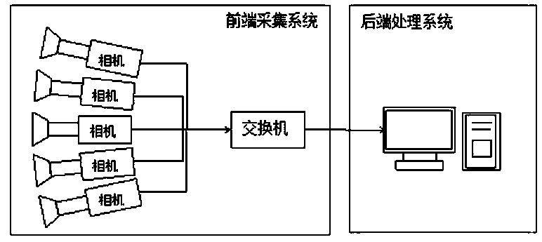
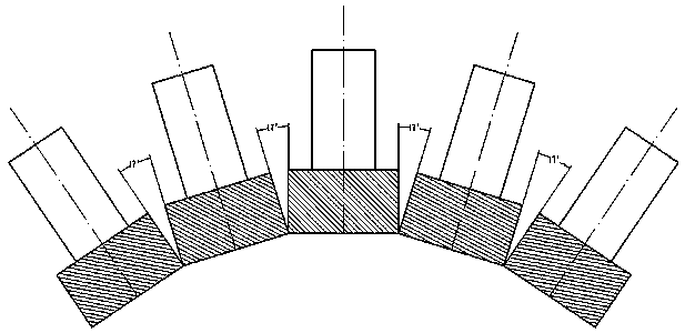
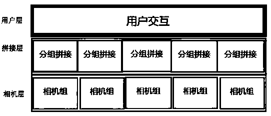
[0038] refer to Figure 1 to Figure 6 As shown, the present invention includes a front-end acquisition system and a back-end processing system. The front-end processing system includes 5 industrial cameras located on the same level and distributed in a fan shape. The 5 industrial cameras are all equipped with high-definition fixed-focus lenses. The plurality of industrial cameras are all connected to a Gigabit network switch; the back-end processing system is composed of computers equipped with splicing system software, and the splicing system software includes a camera layer, a splicing layer and a user layer.

[0039] An image mosaic method, comprising the following steps:

[0040] S1: Determine the overlapping range of each camera position and imaging ...


PUM


Abstract

The invention relates to an image splicing system and an image splicing method, the image splicing system comprises a front-end acquisition system and a rear-end processing system, the front-end processing system comprises five industrial cameras which are located on the same horizontal plane and are distributed in a fan shape, and the industrial cameras are connected with a gigabit network switch; and the rear-end processing system is composed of a computer provided with splicing system software, and the splicing system software comprises a camera layer, a splicing layer and a user layer. Through front-end acquisition system, reasonable placement positions and image overlapping ranges of the industrial cameras are obtained through calculation according to an image splicing method; and consistency of optical centers, the shooting problem of a shot object with the depth of field in a short distance is solved, the overlapped part between the two cameras can be smoothly spliced, the imagedistortion at the edge is small, then the rear-end processing system is connected through the gigabit switch, the calculated image overlapping range is input to carry out multi-thread parallel splicing operation, and a high-resolution image is output.

Description

[0001] (1) Technical field [0002] The invention relates to the field of image processing, in particular to an image splicing system and an image splicing method. [0003] (2) Background technology [0004] Image mosaic technology is mainly used for the generation of large-format high-definition images, using multiple cameras or a single camera at different angles to stitch the images collected, thereby improving the visual range and resolution of the image. Ultra-wide viewing angle images play an irreplaceable role in real life. Although a wide-angle lens can also be used to obtain a wide-angle image, the edge of the wide-angle lens will produce unavoidable distortion. The image stitching technology is proposed to solve the problem that ordinary camera equipment is limited by the shooting angle, and it is impossible to take a wide-angle picture at one time. [0005] With the development of computer and image processing technology, image stitching technology provides a good ...

Claims


Application Information

Patent Timeline
Patent Type & Authority Applications(China)
IPC IPC(8): G06T3/40
CPCG06T3/4038
Inventor 张森王进
Owner JINAN SHENBO INFORMATION TECH
Why Eureka
Try Eureka