
Compact variable reduction ratio electromechanical actuator suitable for various working conditions

An electromechanical actuator and variable deceleration technology, applied in the field of electromechanical servo, can solve the problems of applications that cannot be complex, the reduction ratio cannot be further changed, and the layout scheme of the electromechanical actuator of the transmission cannot be adapted, so as to achieve intelligent control. , the optimal matching of health management, the effect of solving energy demand

Inactive Publication Date: 2019-12-06
BEIJING RES INST OF PRECISE MECHATRONICS CONTROLS
View PDF3 Cites 0 Cited by
  • Summary
  • Abstract
  • Description
  • Claims
  • Application Information

AI Technical Summary

Problems solved by technology

The transmission part of the linear electromechanical actuator adopts a ball screw pair or a planetary roller screw pair, and its lead is selected at the beginning of the design. For the triangle relationship formed by the electromechanical actuator and the installation rocker arm, when After the screw lead and the size of the rocker arm are determined, the reduction ratio of the system cannot be further changed
[0004] When the load condition changes in a large range, the layout scheme of the transmission electromechanical actuator cannot adaptively change the system reduction ratio, thereby changing the output torque and output angle, and cannot be applied in more and more complex ranges, especially for deformation , folding the wings of the aircraft, etc., greatly reducing the scope of application of electromechanical actuators

Method used


Image

  • Compact variable reduction ratio electromechanical actuator suitable for various working conditions

Examples


Embodiment Construction

[0022] Below in conjunction with accompanying drawing and specific embodiment the present invention is described in further detail:

[0023] The purpose of the patent of the present invention is to provide a screw nut as a motor rotor telescopic double-redundancy electromechanical actuator, which realizes the integration and integrated design of the double-redundancy electromechanical actuator, and has short-term advantages compared with existing solutions. The technical characteristics of zero position, small size, light weight, high rigidity, high load capacity, and high precision are especially suitable for the performance requirements of servo actuation systems for military equipment in the aviation field, such as civil airliners, transport aircraft, fighter jets, and drones. In addition, the patented structure and working principle of the present invention can also be applied to electric control devices in the field of ships, which has broad application prospects.

[0024...


PUM


Abstract

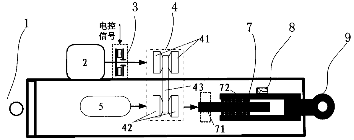
The invention discloses a compact variable reduction ratio electromechanical actuator suitable for various working conditions, and relates to the technical field of electromechanical servo. The actuator comprises a front supporting lug assembly, a rear supporting lug assembly, a servo motor, a brake assembly, a variable reduction ratio speed reducer, a pushing device, a ball screw pair and a rearsupporting lug assembly. The rear supporting lug assembly and the front supporting lug assembly are fixedly installed at the two axial ends of the actuator shell correspondingly. The top end of the variable reduction ratio speed reducer extends out of the actuator shell; an output shaft of the servo motor is in butt joint with the variable reduction ratio speed reducer through the brake assembly.The pushing device is in butt joint with one side of the variable reduction ratio speed reducer; the ball screw pair is horizontally arranged; one axial end of the ball screw pair is fixedly connectedwith the front support lug assembly, and the other axial end of the ball screw pair is in butt joint with the other side of the variable reduction ratio speed reducer. The actuator is compact in structure and has the characteristic of variable reduction ratio; the reduction ratio can be adjusted as required in the working process, and the reduction ratio is increased during low-speed high-torqueoutput; and the reduction ratio is reduced during high-speed low-torque output.

Description

technical field [0001] The invention relates to the technical field of electromechanical servo, in particular to a compact variable reduction ratio electromechanical actuator applicable to various working conditions. Background technique [0002] As an important executive device of the servo system, the electromechanical actuator is used to convert the control command signal output by the system into a torque displacement signal, etc. It is mainly composed of a servo motor, transmission components, sensors, etc., and front and rear connection components. [0003] Common output forms of electromechanical actuators mainly include two types, one is linear, that is, output thrust and displacement; the other is rotary, that is, output torque and rotation angle. The transmission part of the linear electromechanical actuator adopts a ball screw pair or a planetary roller screw pair, and its lead is selected at the beginning of the design. For the triangle relationship formed by the...

Claims


Application Information

Patent Timeline
IPC IPC(8): H02K7/106H02K7/116
CPCH02K7/106H02K7/116
Inventor 宋洪舟牛涛高波韩继文于志远
Owner BEIJING RES INST OF PRECISE MECHATRONICS CONTROLS
Learn More