
Automatic robot assembling method for cylindrical-rectangular composite hole type part

A technology of automatic assembly and assembly method, which is applied in the direction of manipulators, program-controlled manipulators, manufacturing tools, etc., and can solve problems such as difficult assembly strategies, damage to assembly parts and robots, and various contact states

Active Publication Date: 2019-12-10
HARBIN INST OF TECH
View PDF11 Cites 4 Cited by
  • Summary
  • Abstract
  • Description
  • Claims
  • Application Information

AI Technical Summary

Problems solved by technology

[0007] The assembly method described in the present invention is aimed at solving the problem of automatic assembly of hole-like parts with both circular arcs and rectangular straight sides and right angles in the geometric elements, and avoids excessive assembly contact force caused by improper posture between shaft holes during the assembly process damage to assemblies and robots
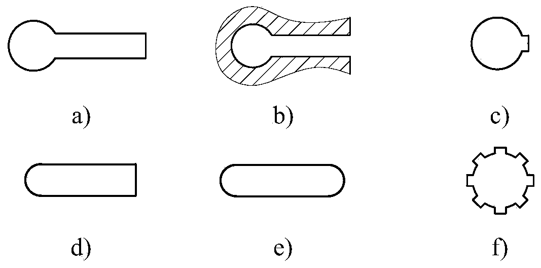
That is to say, in order to solve the problems that the automatic assembly of round-rectangular compound hole parts faces various contact states and difficult to determine the assembly strategy, the present invention refers to such hole parts as round-rectangular compound hole parts , the matching shaft parts are called round-rectangular composite shaft parts. Several common forms of such parts include: flat key hub, spline hub, A-type flat key hole, C-type flat key hole, Special round-rectangular hole, etc.

Method used


Image

  • Automatic robot assembling method for cylindrical-rectangular composite hole type part
  • Automatic robot assembling method for cylindrical-rectangular composite hole type part
  • Automatic robot assembling method for cylindrical-rectangular composite hole type part

Examples


specific Embodiment approach 1

[0082] Embodiment 1: The assembly method is oriented to solving the problem of automatic assembly of hole-like parts with circular arcs, rectangles, straight sides and right angles in the geometric elements, and avoids assembly contact due to improper posture between shaft holes during the assembly process Damage to the assembly and robot due to excessive force. Such hole parts are called round-rectangular compound hole parts, and the matching shaft parts are called round-rectangular compound shaft parts. figure 1 Several common forms of such parts are given, including flat key hub, spline hub, A-type flat key hole, C-type flat key hole, special round-rectangular hole and so on.

[0083] Among the common parts in engineering practice, there are round-rectangular compound hole / shaft parts: splines, A-type flat keys, C-type flat keys, etc.

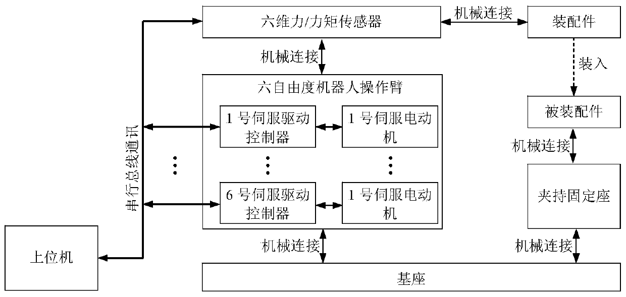
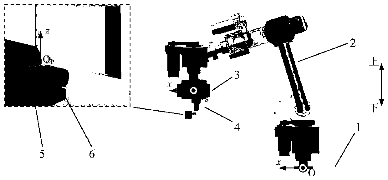
[0084] like figure 2 As shown, the automatic assembly system for round-rectangular composite hole parts using the assembly method is co...

specific Embodiment approach 2

[0088] Specific embodiment two: In the assembly method of the circular-rectangular composite hole parts, the six-degree-of-freedom robot 2 needs to perform the position and orientation of the assembly part 4 according to the force feedback information measured by the six-dimensional force / torque sensor 3 Adjust it so that it is finally loaded into the circle-rectangular compound hole of the assembled part 6. The above assembly process is divided into three stages: approach stage, hole search stage, and insertion stage. The flow chart of assembly is as follows: Figure 4 shown, where F z Represents the z-axis force component measured by the six-dimensional force / torque sensor 3 (transformed into the ΣOP system), h represents the distance of the assembly part 4 inserted into the assembled part 6 along the z-axis, h d and h max are the insertion depth discrimination thresholds for hole search completion and assembly completion, F max is the threshold of contact force.

[0089] ...

specific Embodiment approach 3

[0095] Specific implementation mode three: In the automatic assembly system applying the assembly method of the circular-rectangular composite hole parts, it is necessary to construct such Figure 5 For the force / position hybrid control system shown, define X=[x,y,z,θ P1 ,θ P2 ,θ P3 ] T is the pose vector of assembly 4, where x, y, z are ΣO P Position coordinates in the base coordinate system ΣO, θ P1 , θ P2 , θ P3 ΣO P The three Euler angles of the system relative to the ΣO system; θ=[θ 1 ,θ 2 ,θ 3 ,θ 4 ,θ 5 ,θ 6 ] T and τ=[τ 1 ,τ 2 ,τ 3 ,τ 4 ,τ 5 ,τ 6 ] T are respectively defined as the joint angle and joint driving torque vector of the six-DOF robot 2, where θ i and τ i (i=1,2,...,6) respectively represent the joint angle and driving moment of the i-th joint; S f e is a six-dimensional force / torque sensor 3 in ΣO S The raw data of force rotation (including three force components and three moment components) measured in the system, P f e will be S...


PUM


Abstract

The invention discloses an automatic robot assembling method for a cylindrical-rectangular composite hole type part, and relates to the technical field of robot assembly control. The invention aims tosolve the problems that the automatic assembly of the cylindrical-rectangular composite hole type part faces various contact states, and the assembly strategy is difficult to determine. The inventiondiscloses an automatic assembling method for a cylindrical-rectangular composite hole type part to perform contact state judgment according to force feedback information and carry out corresponding adjustment aiming at different contact states. A assembly process is divided into an approach stage, a hole searching stage and an insertion stage; a five-time spline trajectory planning method is usedin the approach stage to enable the part to be assembled to be quickly close to the assembled part; the hole searching stage has four contact states; the contact states of the insertion stage are divided into 7 kinds of 41 types according to the number and the relative positions of the contact points, stress analysis is carried out on each contact state and a corresponding hole searching or insertion assembly strategy is provided, and the assembling simulation of the cylindrical-rectangular composite hole type part is carried out; and the result shows that the assembling method can complete assembly on the premise that the contact force is too large.

Description

technical field [0001] The invention relates to a robot automatic assembly strategy and method for parts with irregular shapes (round-rectangular composite holes), and relates to the technical field of robot assembly control. Background technique [0002] Assembly is an important link in the product manufacturing process, and the quality of assembly often directly affects the quality of the final product. At present, there are still a large number of assembly tasks in the industrial production process that still need to be completed by manual assembly operations. However, there are many problems in manual assembly, for example, high work intensity, low work efficiency, high error rate, high cost and so on. Faced with these problems, the manufacturing industry has an increasingly urgent need to use robots to replace manual assembly operations. Robot assembly can not only improve production efficiency, but also has a wider range of applications, such as in hazardous environm...

Claims


Application Information

Patent Timeline
IPC IPC(8): B25J9/16
CPCB25J9/1633B25J9/1687
Inventor 吴伟国高力扬王通
Owner HARBIN INST OF TECH
Learn More