A vane type servo swing hydraulic cylinder and its mechanical equipment

A technology for swinging hydraulic cylinders and mechanical equipment, applied in the direction of fluid pressure actuating devices, etc., can solve problems such as increased wear, increased leakage, and increased leakage, and achieves the effect of preventing contact and improving dynamic control performance.

Active Publication Date: 2018-05-25
烟台比吉流体控制技术有限公司
View PDF5 Cites 0 Cited by
  • Summary
  • Abstract
  • Description
  • Claims
  • Application Information

AI Technical Summary

Problems solved by technology

However, the oscillating hydraulic cylinders disclosed in the prior art have some insurmountable shortcomings in some special application environments: 1. In high-frequency use environments, the high-speed friction between the stator and the rotor or the sealing material and the stator-rotor causes serious heating. 2. Long-term use in a high-frequency environment will aggravate wear and shorten the service life, and wear will also cause increased leakage. 3. The existing vane-type swing cylinder can only withstand torque. When there is a large axial load , will intensify the friction between the side of the blade and the two ends of the cover, and cause heat and wear for a long time; when there is a large radial load, it will increase the contact pressure between the drive shaft and the bearing, thereby increasing wear and heating severe, unable to work long hours
4. When high-precision dynamic control is required, the requirements for the starting friction of the swing cylinder are very high. It requires both extremely low leakage and very low friction control, which puts forward extremely high requirements for processing conditions. Difficult, difficult to successfully process and assemble, the existing structure will also have problems such as wear, heat generation, and increased leakage during high-speed operation
It is also based on this structural difference that although the prior art has proposed the technical inspiration of applying the static pressure support technology to the linear hydraulic cylinder, there is no reasonable structure to apply the static pressure support technology to the swing hydraulic cylinder.

Method used


Image

  • A vane type servo swing hydraulic cylinder and its mechanical equipment
  • A vane type servo swing hydraulic cylinder and its mechanical equipment
  • A vane type servo swing hydraulic cylinder and its mechanical equipment

Examples


Embodiment Construction

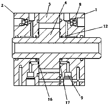
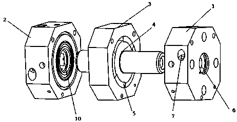
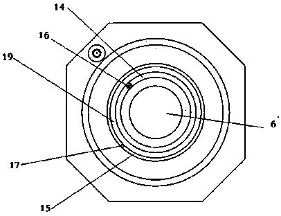
[0025] combine Figure 1 to Figure 5As shown, a vane-type servo swing hydraulic cylinder of the present invention and its mechanical equipment include a front end cover 1, a rear end cover 2, a stator 3 and a rotor 4, the stator and the rotor are assembled between the front end cover and the rear end cover, The rotor is placed inside the stator. There are four oil chambers 5 between the blades of the rotor and the stator. The front end cover 1 and the rear end cover 2 are provided with shaft holes 6. A high-pressure oil source oil inlet hole 7, four radial bearing restrictors 8 and one thrust bearing restrictor 9 are installed in the front end cover 1 and the rear end cover 2, and the shaft holes of the front end cover 1 and the rear end cover 2 is provided with 4 radial bearing oil outlet holes 10, the oil outlet ends of the 4 radial bearing throttles 8 are connected to 4 radial bearing oil outlet holes 10, the end faces and shafts of the front end cover 1 and the rear end co...


PUM


Abstract

The invention belongs to the field of machinery manufacturing and particularly relates to a blade type servo swing hydraulic cylinder and mechanical equipment with the same. The blade type servo swing hydraulic cylinder comprises a front end cover, a rear end cover, a stator and a rotor, the stator and the rotor are mounted between the front end cover and the rear end cover, the rotor is arranged in the stator, and N oil cavities are formed between the rotor and the stator. By arrangement of oil ways in the front end cover and the rear end cover and regulation compensation of throttling valves, radial hydrostatic bearings and axial thrust hydrostatic bearings are formed between the end covers and the rotor, and low-friction starting, unbalance loading resistance, low friction and the like are realized. In addition, reasonable structure, assembly difficulty lowering and assembly space reduction are realized, an application range is effectively expanded, a swing cylinder assembly gap is further narrowed, oil leakage is prevented, and significance in use of precision equipment is achieved.

Description

technical field [0001] The invention belongs to the mechanical field, in particular to a vane type servo swing hydraulic cylinder and mechanical equipment using the same. Background technique [0002] Swing hydraulic cylinders are divided into spiral swing cylinders and vane swing cylinders. Among them, the latest and more representative prior art of spiral swing cylinders is: the bipolar helicoid swing oil cylinder disclosed by the publication number CN105275910A, and the public number CN102322457A- A telescopic rotary hydraulic cylinder, the basic principle of which is a special hydraulic cylinder that uses a helical pair with a large helix angle to achieve rotational motion. The helical rod of the output shaft and the cylinder body are fixed with two degrees of freedom by bearings. The helical teeth of the rod mesh, and the surface shape of the helical rod of the output shaft is the same as that of the outer surface of the piston. By supplying oil to both sides of the pi...

Claims


Application Information

Patent Timeline
Patent Type & Authority Patents(China)
IPC IPC(8): F15B15/12F15B15/20
CPCF15B15/12F15B15/20
Inventor 刘虎赵延刚刘光伟王御杰刘琛宇
Owner 烟台比吉流体控制技术有限公司
Why Eureka
Try Eureka