Hybrid power drive system

A driving system and hybrid technology, applied in hybrid vehicles, power devices, pneumatic power devices, etc., can solve the problem of high cost

Pending Publication Date: 2019-12-10
GUANGZHOU AUTOMOBILE GROUP CO LTD
View PDF0 Cites 2 Cited by
  • Summary
  • Abstract
  • Description
  • Claims
  • Application Information

AI Technical Summary

Problems solved by technology

However, this system requires two independent subsystems, and the cost is high

Method used


Image

  • Hybrid power drive system
  • Hybrid power drive system
  • Hybrid power drive system

Examples


no. 1 example

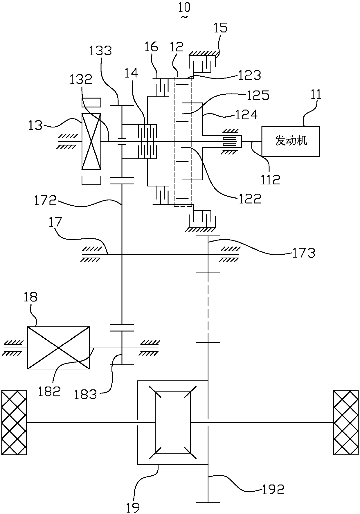
[0039] figure 1 It is a structural schematic diagram of the hybrid drive system according to the first embodiment of the present invention. Such as figure 1 As shown, the hybrid drive system 10 includes an engine 11 , a planetary gear device 12 , a first motor 13 , a switch device, an intermediate shaft 17 , a second motor 18 , a differential 19 and a power battery (not shown).

[0040] The engine 11 has an engine output shaft 112 . In this embodiment, the engine 11 is, for example, a gasoline engine or a diesel engine.

[0041] The planetary gear device 12 includes a first rotation element, a second rotation element, and a third rotation element. The first rotary element is connected to the first motor 13 , and the second rotary element is connected to the engine 11 . In this embodiment, the first rotating element 122 is, for example, the sun gear 122 , the second rotating element is, for example, the planet carrier 124 , and the third rotating element is, for example, th...

no. 2 example

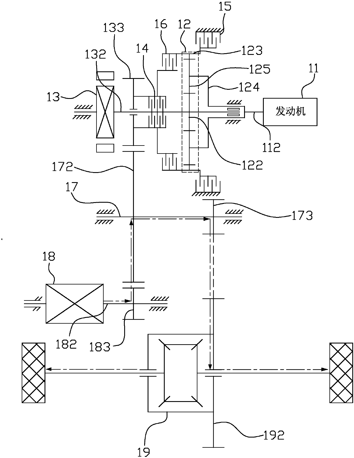
[0064] Figure 11 It is a structural schematic diagram of the hybrid drive system according to the second embodiment of the present invention. Such as Figure 11 As shown, the hybrid drive system 10 of the present embodiment has substantially the same structure as the hybrid drive system 10 of the first implementation force, except that the installation positions of the first clutch 14 and the second clutch 16 are different.

[0065] Specifically, the first clutch 14 and the second clutch 16 are arranged in the same housing, and the first clutch 14 and the second clutch 16 are arranged coaxially. Since the first clutch 14 and the second clutch 16 are integrated in one housing, the volume occupied by the first clutch 14 and the second clutch 16 can be greatly reduced, and space is reserved for the arrangement of other components of the engine.

no. 3 example

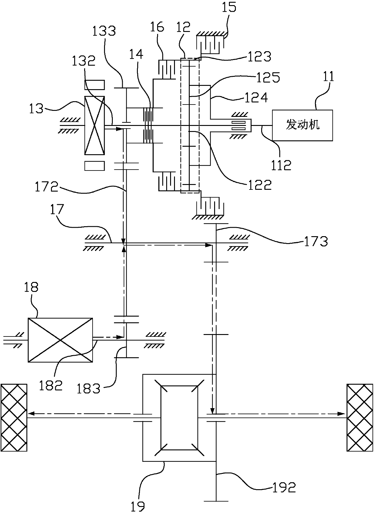
[0067] The hybrid drive system 10 of the present embodiment has substantially the same structure as the hybrid drive system 10 of the first embodiment, except that the connection relationship between the engine 11 and the planetary gear device 12 and the connection relationship between the clutch gear device and the planetary gear device 12 are different. .

[0068] Specifically, in this embodiment, the first rotating element is a sun gear, the second rotating element is a ring gear, the third rotating element is a planetary carrier, and the switching device is a brake or a one-way clutch, that is to say, the ring gear 123 and The engine output shaft 112 is connected, and the second clutch 16 is fixed on the planet carrier 124 . Please refer to the first embodiment for the connection relationship and driving method of the components of the hybrid drive system 10 .

[0069] The hybrid drive system 10 of this embodiment has a first-level pure electric mode, a second-level pure ...


PUM


Abstract

A hybrid power drive system comprises an engine, a first motor, a second motor, a planetary gear device, a clutch gear device and a switch device, wherein the engine and the first motor are both connected with the planetary gear device, and the clutch gear device is arranged between the first motor and the planetary gear device; the planetary gear device comprises a first rotating element, a second rotating element and a third rotating element, the first rotating element is connected with the first motor, and the second rotating element is connected with the engine; the clutch gear device comprises a first clutch, a second clutch, as well as a clutch gear and an engaging element which are connected to the first clutch, the clutch gear is connected to an output end, the second clutch is connected with the third rotating element, and the second clutch is used for engaging the third rotating element and the engaging element; the switching device is used for locking or unlocking the thirdrotating element; the second motor is arranged in parallel with the first motor, and the second motor is connected to the output end. The hybrid power drive system is good in platformization.

Description

technical field [0001] The invention relates to the technical field of new energy, in particular to a hybrid drive system. Background technique [0002] At present, there are two main types of transmissions on the market: stepped transmissions and continuously variable transmissions. Stepped transmissions are subdivided into manual and automatic. Most of them provide a limited number of discrete output and input speed ratios through different meshing arrangements of gear trains or planetary gear trains. The adjustment of the driving wheel speed between two adjacent speed ratios is realized by the speed change of the internal combustion engine. CVT, whether it is mechanical, hydraulic, or electromechanical, can provide an infinite number of continuously selectable speed ratios within a certain speed range. In theory, the speed change of the driving wheel can be completely completed through the transmission. . In this way, the internal combustion engine can work in the opt...

Claims


Application Information

Patent Timeline
Patent Type & Authority Applications(China)
IPC IPC(8): B60K6/365B60K6/38B60K6/26
CPCB60K6/365B60K6/38B60K6/26B60K6/387B60K6/442B60K6/547B60K2006/381B60K6/445Y02T10/62B60K2006/4816B60K2006/4825
Inventor 杨勇赵江灵尚阳董泽庆祖国强苏倩汝
Owner GUANGZHOU AUTOMOBILE GROUP CO LTD
Why Eureka
Try Eureka