
Pantograph structure

A pantograph and bow head technology, which is applied in the field of electrified railway pantograph-catenary system, can solve the problems of low optimization degree and severe pantograph-catenary vibration, and achieve prolonging service life, suppressing pantograph-catenary vibration, and easy realization Effect

Inactive Publication Date: 2019-12-10
SOUTHWEST JIAOTONG UNIV
View PDF26 Cites 4 Cited by
  • Summary
  • Abstract
  • Description
  • Claims
  • Application Information

AI Technical Summary

Problems solved by technology

However, the above-mentioned technologies are mostly limited to the original pantograph structure itself, and its optimization degree is small, and the boundary restriction conditions are gradually clear and even reach the bottleneck, which cannot fundamentally solve the problem of severe pantograph-catenary vibration

Method used


Image

  • Pantograph structure
  • Pantograph structure
  • Pantograph structure

Examples


Embodiment Construction

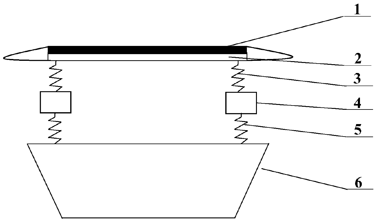
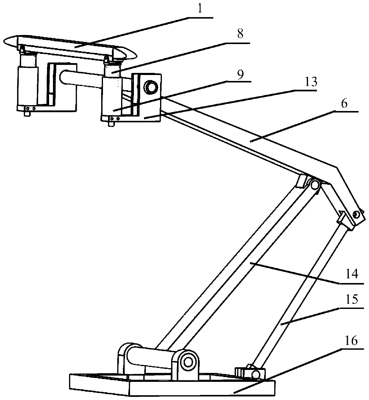
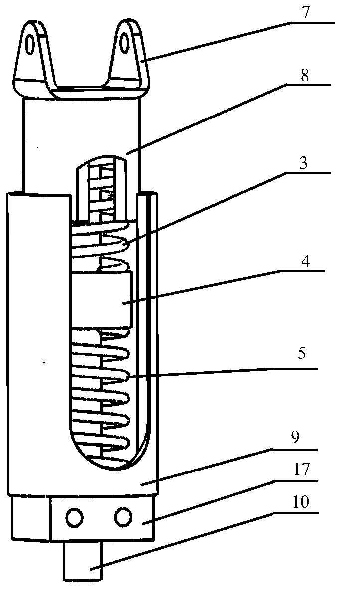
[0025] The present invention will be further described in detail below in conjunction with the examples, and the specific examples described here are only for explaining the present invention, rather than limiting the present invention. A pantograph structure, comprising a carbon block 1 for a skateboard, an aluminum support for a skateboard 2, an upper arm 6, a lower arm 14 and a pantograph base 16, the upper end of the lower arm 14 and the lower part of the turning point at the tail of the upper arm 6 The hinge support is hinged, and the lower end is an inverted "T"-shaped structure, and the two ends of the inverted "T"-shaped crosspiece are hinged with the lugs at the front of the middle and front parts of the pantograph base 16; the upper end of the tie rod 15 is connected with the upper arm 6 The hinge support at the rear end is hinged, and the lower end is hinged with the hinge support in the middle of the rear transom of the pantograph base 16; the upper end of the upper...


PUM


Abstract

The invention discloses a pantograph structure, and belongs to the technical field of electrified railway pantograph-contact network systems. The upper end of an upper arm rod is of a T-shaped structure, two ends of the T-shaped cross piece are respectively provided with an L-shaped sliding plate bracket respectively, the vertical arm of each L-shaped sliding plate bracket is hinged with the upperarm rod, the front end of the cross arm is provided with a vertical socket matched with a bottom mounting seat of the outer cylinder of a spring cylinder, and the vertical socket is fixed with the bottom mounting seat of the outer cylinder of the spring cylinder through bolts; the bottom mounting seat is provided with a central guide rod, and the upper end of the central guide rod is provided with a double-lug support seat fixed at the bottom; the bottom end of a secondary suspension spring is in contact with the bottom mounting seat, the upper end of the secondary suspension spring is fixedwith the lower end face of a matched mass block, the lower end face of a primary suspension spring is fixed with the upper end face of the matched mass block, coaxial through holes are formed in double lugs of the double-lug support seat, and the inner cylinder of the spring cylinder is fixed with the lower part of the double-lug support seat. The pantograph structure is mainly used for receivingcurrent of an electric drive train.

Description

technical field [0001] The invention belongs to the technical field of electrified railway pantograph-catenary systems. Background technique [0002] In high-speed electrified railways, the pantograph installed on the roof of the train and the catenary erected next to the track line realize the transmission of electric energy through sliding contact. The degree of vibration and shock of the system and the life of the pantograph frame structure have become the focus of attention in the pantograph-catenary field. The trunk line railway adopts flexible catenary, and its pantograph-catenary interaction performance is good, but as the train running speed increases, the vibration and impact of the pantograph-catenary system will intensify; the urban rail transit runs at a relatively low speed, and due to the characteristics of low voltage and high current, rigid catenary system is often used. The catenary has a relatively large impact during the dynamic operation of the pantograp...

Claims


Application Information

Patent Timeline
Patent Type & Authority Applications(China)
IPC IPC(8): B60L5/22B60L5/28B60L5/30B60L5/32
CPCB60L5/22B60L5/28B60L5/30B60L5/32
Inventor 王江文梅桂明张卫华
Owner SOUTHWEST JIAOTONG UNIV
Learn More